Output-floating input-parallel high-gain Boost converting circuit and switching method thereof

A conversion circuit and high-gain technology, applied in the field of output floating input parallel high-gain Boost conversion circuit, can solve the problems of low voltage gain, large input current and voltage ripple, etc., to reduce ripple and increase voltage gain , Improve the effect of the boost effect

Active Publication Date: 2017-12-26
镇江市睿驰环保科技有限公司
View PDF0 Cites 13 Cited by
  • Summary
  • Abstract
  • Description
  • Claims
  • Application Information

AI Technical Summary

Problems solved by technology

[0005] The present invention aims at problems such as the low voltage gain of the existing boost converter, the Boost converter working at the limit duty cycle under high gain, and the re

Method used


Image

  • Output-floating input-parallel high-gain Boost converting circuit and switching method thereof
  • Output-floating input-parallel high-gain Boost converting circuit and switching method thereof
  • Output-floating input-parallel high-gain Boost converting circuit and switching method thereof

Examples


Embodiment Construction

[0050] The following will clearly and completely describe the technical solutions in the embodiments of the present invention with reference to the drawings in the embodiments of the present invention.

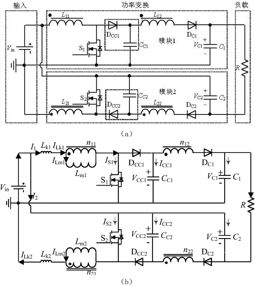
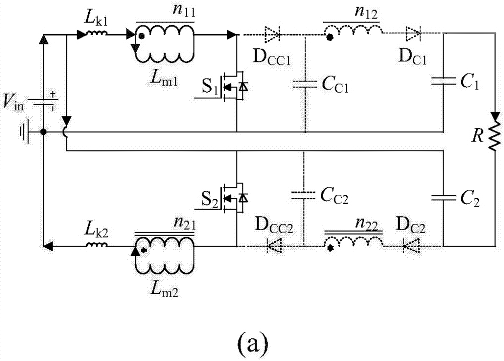
[0051] Such as figure 1 As shown in (a), an output floating input parallel high-gain Boost conversion circuit includes two windings L p1 , L s1 The coupled inductance M 1 , with two windings L p2 , L s2 The coupled inductance M 2 , two power switches S 1 , S 2 , two clamping diodes D CC1 、D CC2 , two clamping capacitors C C1 、C C2 , two output diodes D C1 、D C2 , the output capacitance C 1 and C 2 ;

[0052] An output floating input parallel high-gain Boost conversion circuit is characterized in that: it includes three parts: input, power conversion, and load; the power conversion part is composed of module one and module two, and the structure of module one and module two is symmetrical; wherein Primary winding L of the first coupled inductor in module 1 11 ,...


PUM


Abstract

The invention discloses an output-floating input-parallel high-gain Boost converting circuit and a switching method thereof and belongs to the field of power electronics. The output-floating input-parallel high-gain Boost converting circuit consists of an input portion, a power conversion portion and a load portion, wherein the power conversion portion can be divided into a first module and a second module which are in structural symmetry. A converter comprises a coupling inductor M1 with two windings L11 and L12, a coupling inductor M2 with two windings L21 and L22, two power switching tubes S1 and S2, two clamping diodes DCC1 and DCC2, two clamping capacitors CC1 and CC2, two output diodes DC1 and DC2 and two output capacitors C1 and C2. On the basis of the output-floating input-parallel high-gain Boost converting circuit, the boost characteristic of the coupling inductors is combined with series-connection boost effects of the output capacitors. The output-floating input-parallel high-gain Boost converting circuit and the switching method thereof have the advantages that the problem that a traditional Boost circuit is limited in voltage gain is solved, the converting circuit is easily to be expanded into multiple phases, and input current ripples can be reduced effectively through application of an interleaving switch-on technology to the switching tubes in the two modules.

Description

technical field [0001] The invention belongs to the field of DC-DC conversion circuits of power electronics technology, and in particular relates to an output floating input parallel high-gain Boost conversion circuit and a switching method. Background technique [0002] With the increasing global energy crisis and environmental pollution, renewable energy sources such as solar energy, wind energy, geothermal energy, and biomass energy have attracted worldwide attention. However, due to the influence of environment, temperature and other factors, the output voltage of renewable energy is low and fluctuates greatly. In practical applications, a variety of energy combinations are often required to ensure the stability and practicability of renewable energy power generation. To achieve the DC bus voltage required by the grid-connected inverter, a high-gain boost converter is required in practical applications to boost the output voltage of renewable energy. [0003] Commonly u...

Claims


Application Information

Patent Timeline
IPC IPC(8): H02M3/07H02M1/14
CPCH02M1/14H02M3/07H02M1/0067H02M1/0083
Inventor 廖志凌吴超顾赟崔清华张凯
Owner 镇江市睿驰环保科技有限公司
Why Eureka
Try Eureka