A Multi-stage Tidal Energy Turbine Based on Real-time Adjustable Spindle Angle

A shroud, tidal energy technology, applied in mechanical equipment, hydroelectric power generation, ocean energy power generation, etc., can solve the problem that the water energy flowing through the runner cannot be well utilized, the design of the shroud attack angle is limited, and the real-time Adjust the shroud and other issues to achieve a significant energy enhancement effect, improve the inflow effect, and improve the effect of energy harvesting

Active Publication Date: 2019-07-30
HOHAI UNIV
View PDF7 Cites 0 Cited by
  • Summary
  • Abstract
  • Description
  • Claims
  • Application Information

AI Technical Summary

Problems solved by technology

However, this solution still has the following deficiencies: first, the structure of the dome is simple, and the angle of attack of the dome cannot be adjusted in real time according to the inflow angle, so it cannot play a good role in energy gathering and directly affects economic performance; Class ocean current energy turbines, the efficiency of using ocean current energy to generate electricity is low
Although this scheme can efficiently convert ocean kinetic energy under the bidirectional flow of ocean currents, it still has the following shortcomings: first, it belongs to a single-stage ocean current energy turbine, and the efficiency of using ocean current energy to generate electricity is low; second, the design of turbine blades is still traditional Design, the airfoil is too simple, can not make good use of the water energy flowing through the runner; third, the design of the angle of attack of the dome is limited, and the dome cannot be adjusted in real time
Although the use of the shroud improves the energy gathering effect of the tidal current energy, there are still the following deficiencies: First, the vertical axis blade adopts a single elliptical blade design, which cannot provide efficient output power; second, it belongs to a single-stage ocean current energy turbine. The efficiency of ocean current power generation is low

Method used


Image

  • A Multi-stage Tidal Energy Turbine Based on Real-time Adjustable Spindle Angle
  • A Multi-stage Tidal Energy Turbine Based on Real-time Adjustable Spindle Angle
  • A Multi-stage Tidal Energy Turbine Based on Real-time Adjustable Spindle Angle

Examples


Embodiment 1

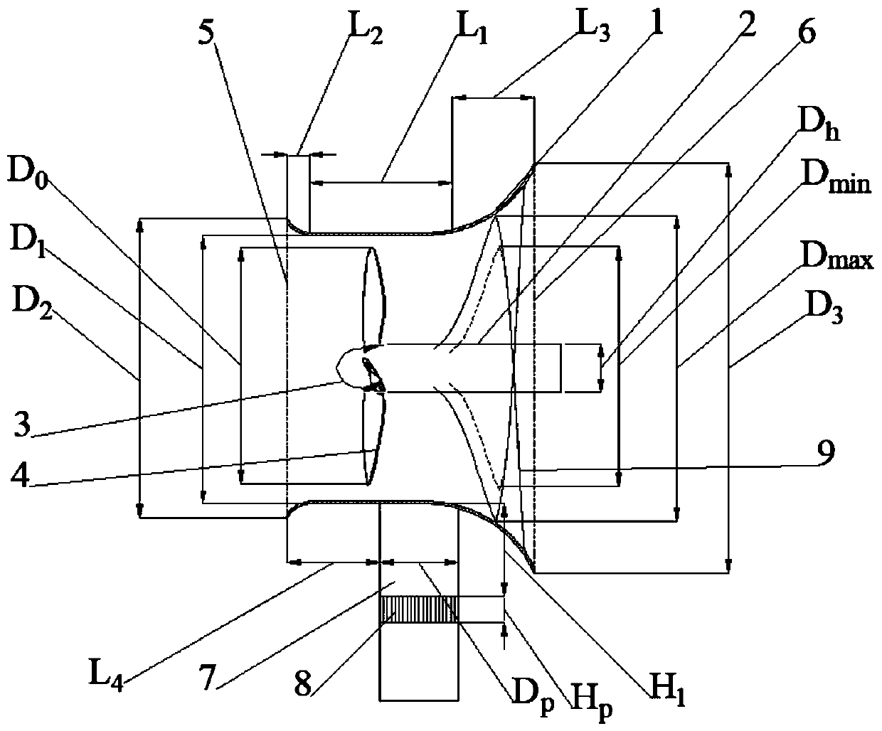
[0042] combine Figure 1 to Figure 10 , the present invention proposes a multi-stage tidal energy turbine based on the real-time adjustable deflector rotation angle, which includes a deflector 1, a hub 3 fixed on the rotating shaft 2, and a basic impeller fixed on the hub 3. The rotating shaft 2, the hub 3 and the basic impeller are all arranged in the shroud 1, which also includes a support shaft 7 with a real-time adjustable rotation angle of the shroud 1, and a hyperbolic helical helical blade 9 with a variable radius. The energy-increasing runner, the energy-increasing runner is located at the outlet end of the shroud 1, and the hyperbolic spiral blade 9 is gradually stretched along the axial direction of the rotating shaft 2 according to the helix of the hyperbolic spiral, It is in the shape of spatial intersecting twist and is evenly distributed on the circumferential inner wall of the rotating shaft 2, and the intersection of the cross-sections of the hyperbolic helical...

Embodiment 2

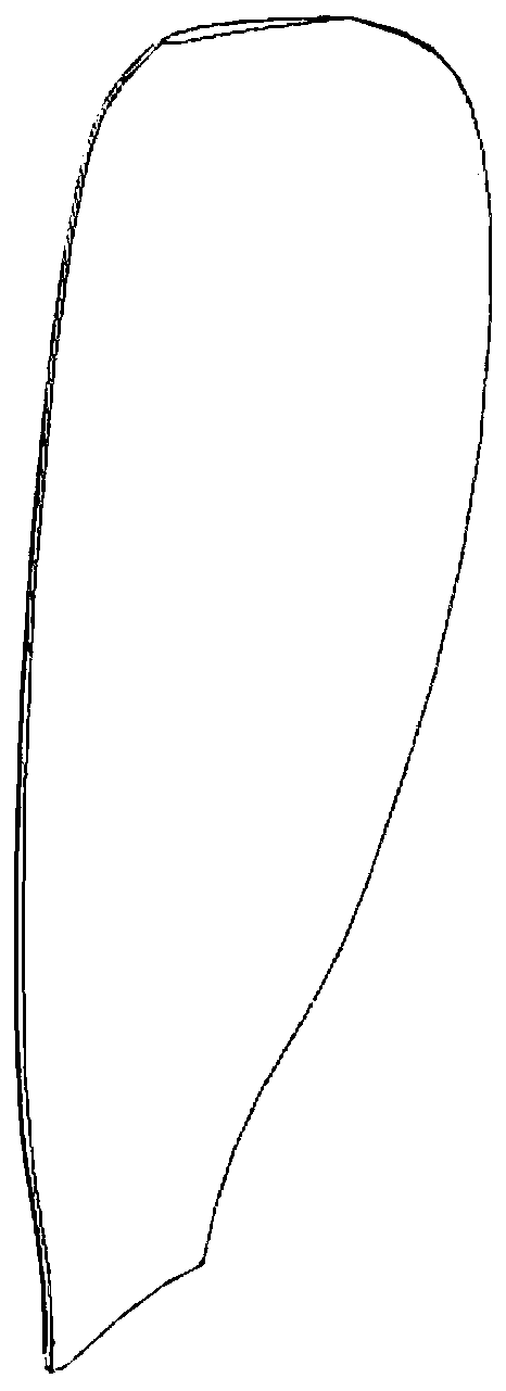
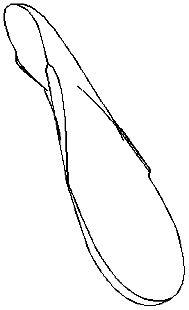
[0057] combine Figure 2 to Figure 5 The parameters of the installation angle of each section of the twisted blade 4 according to the present invention are shown in Table 3, and the parameters of the chord length of each section of the twisted blade 4 are shown in Table 4.

[0058] table 3:

[0059] Section number Installation angle(°) Section number Installation angle(°) 1002 40.14 1012 20.29 1003 38.23 1013 18.67 1005 35.27 1015 15.63 1006 32.69 1016 14.13 1007 30.23 1017 12.58 1008 27.94 1018 10.86 1009 25.81 1019 8.66 1010 23.84 1020 5.92

[0060] The installation angle from the blade root to the blade tip is fitted to the sixth power of the number of sections, and the installation angle fitting equation is:

[0061] Y=-9.21×10 -7 x 6 +8.33×10 -5 x 5 -3.71×10 -3 x 4 +8.39×10 -2 x 3 -0.899x 2 +2.06x+38.86;

[0062] Table 4:

[0063]

[0064]

[0065] The chord length of the distort...

Embodiment 3

[0068] combine figure 1 , the shape of the hub 3 of the present invention is a spherical convex, the length L of the hub 3 0 The length L of the middle section with the shroud 1 1 The ratio of 0.29 to 0.36, the length L of the inlet section of the shroud 1 2 The length L of the middle section with the shroud 1 1 The ratio of 0.08 to 0.15, the length L of the outlet section of the shroud 1 3 The length L of the middle section with the shroud 1 1 The ratio of 0.51 to 0.58, the diameter Dp of the support shaft 7 and the total length of the shroud 1 (L 1 +L 2 +L 3 ) ratio is 0.2 to 0.3, the distance from the center of the support shaft 7 to the front end of the shroud 1 (L 4 +0.5Dp) and the total length of the shroud 1 (L 1 +L 2 +L 3 ) ratio is 0.45 to 0.65, the distance H between the hydraulic turntable bearing 8 and the lower part of the shroud 1 1 The ratio to the diameter Dp of the support shaft 7 is 1.2-2.6, and the ratio of the height Hp of the hydraulic slewing ...


PUM


Abstract

Provided is a multi-stage tidal current energy water turbine based on a real-time adjustable guide cover rotation angle, the water turbine comprising a guide cover (1), a hub (3), which is fixedly arranged on a rotary shaft (2), and a basic impeller, which is fixedly arranged on the hub (3), and further comprising a supporting shaft (7) capable of adjusting the rotation angle of the guide cover in real time, and an energized rotary wheel with variable-radius hyperbolic spiral blades (9), wherein the hyperbolic spiral blades (9) gradually extend in an axial direction of the rotary shaft (2) according to the spiral line of a hyperbolic spiral line, are spatially intersected and twisted, and are uniformly distributed on an inner circumferential wall of the rotary shaft (2). The water turbine has a simple structure and is efficient, and not only can same be used for power generation using ocean tidal current energy, but same can also be used for power generation under conditions of a minute amount of tidal current energy from streams in a mountainous area, a mountain spring, a small reservoir, etc.

Description

technical field [0001] The invention belongs to the technical field of fluid machinery and hydropower engineering equipment, in particular to a multi-stage tidal current energy water turbine based on a real-time adjustable deflector angle. Background technique [0002] Countries in the world today put the development of hydropower in the priority position of energy development. The total amount of hydropower resources in my country is very rich. There are not only medium and high water head resources, but also low water head resources (including tidal current energy) of about 0.8 to 100 million kilowatts. The development and utilization of new energy, especially the development and utilization of marine energy for power generation, has great potential. development potential. Ocean current energy generates electricity by relying on the impact of the ocean tide to rotate the water turbine at high speed, and then drive the generator to generate electricity. It does not require ...

Claims


Application Information

Patent Timeline
Patent Type & Authority Patents(China)
IPC IPC(8): F03B13/26F03B3/12F03B3/18
CPCF03B3/121F03B3/18F03B13/264F05B2250/15F05B2270/602Y02E10/20Y02E10/30
Inventor 张玉全郑源李东阔臧伟杨春霞
Owner HOHAI UNIV
Why Eureka
Try Eureka