Rotary electric machine

A technology for rotating motors and separating components, which is applied in the direction of electrical components, electromechanical devices, and electric components. It can solve the problems of reduced dimensional accuracy of rectification structures, dimensional changes, and difficulty in obtaining sufficient rectification effects, etc., to achieve improved cooling effects, reliable positioning, The effect of preventing positional misalignment

Active Publication Date: 2017-12-29
HONDA MOTOR CO LTD
View PDF5 Cites 4 Cited by
  • Summary
  • Abstract
  • Description
  • Claims
  • Application Information

AI Technical Summary

Problems solved by technology

[0009] However, in the aforementioned techniques, due to factors such as press-fitting of the stator components, thermal deformation due to welding, etc., the dimensional accuracy of the rectification structure is reduced, and it may be difficult to obtain a sufficient rectification effect.

Method used


Image

  • Rotary electric machine
  • Rotary electric machine
  • Rotary electric machine

Examples


Embodiment Construction

[0056] Hereinafter, embodiments of the present invention will be described with reference to the drawings.

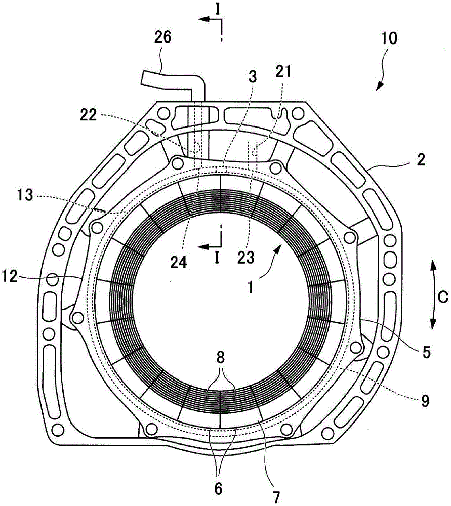
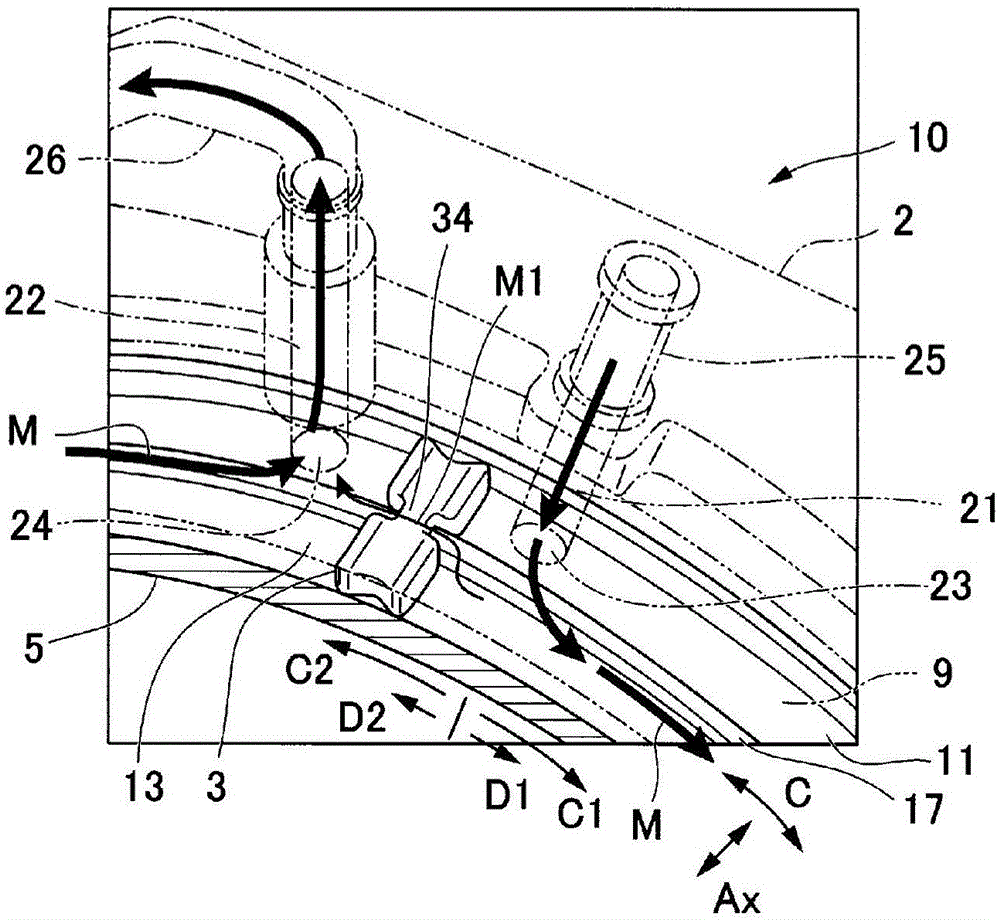
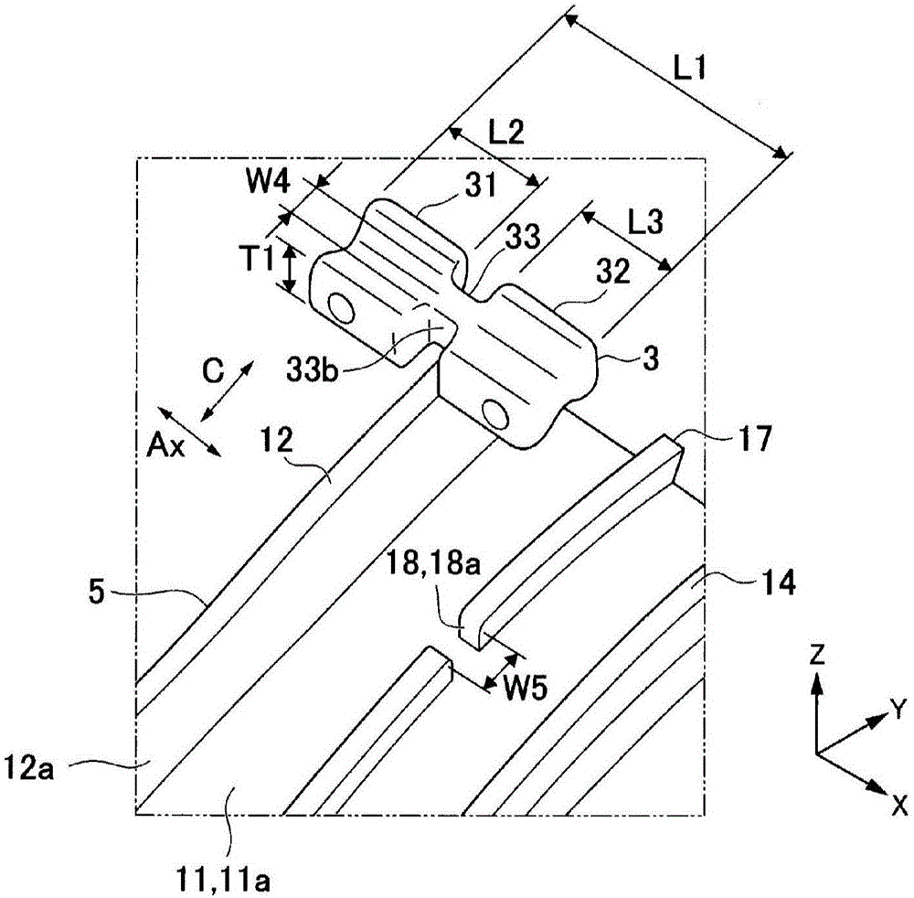
[0057] figure 1 It is a front view of the rotating electric machine 10 of embodiment. figure 2 It is a perspective view showing a part of the stator bracket 5 and the housing 2 . image 3 It is a perspective view showing the stator bracket 5 and the partition member 3 . Figure 4 It is a sectional view showing a part of the stator bracket 5 and the housing 2 . Figure 5 ~ Figure 9 It is a figure which shows the stator holder 5 and the partition member 3. Arrow Ax indicates a direction along the axis of the stator 1 . Arrow R indicates the radial direction of the stator 1 . Arrow C indicates a direction around the axis of the stator 1 (circumferential direction).

[0058] The rotary electric machine 10 can be used for vehicle drive and regenerative power generation of, for example, an electric vehicle, a hybrid vehicle, and the like. Inside the stator 1, a rotata...


PUM


Abstract

The invention provides a rotary electric machine having full rectification, easy to manufacture and having excellent durableness. The rotary electric machine (10) includes a stator, a passage (13), an inlet opening (23), an outlet opening (24), and a partition (3). The stator has an outer periphery. The passage is provided around the outer periphery. A cooling medium (M) is to flow through the passage. The inlet opening (23) is connected to the passage. The cooling medium (M) is to be supplied to the passage via the inlet opening. The outlet opening (24) is connected to the passage. The cooling medium is to be discharged from the passage (13) via the outlet opening. The inlet opening and the outlet opening divide the passage into a longer passage and a shorter passage shorter than the longer passage. The partition (3) is provided in the shorter passage and comprises an elastic material to contact with an inner surface of the shorter passage (3) so as to restrict a flow of the cooling medium.

Description

technical field [0001] The invention relates to a rotating electric machine. Background technique [0002] A rotating electrical machine including a stator and a case housing the stator is used in a hybrid vehicle or the like. For example, a rotating electric machine has been proposed in which a refrigerant flow path is formed between a stator and a housing (for example, refer to Patent Document 1). [0003] In a rotating electric machine having a flow path for refrigerant, a rectification structure such as a partition member that defines the flow direction of the refrigerant may be provided in the flow path (for example, refer to Patent Document 2). [0004] prior art literature [0005] patent documents [0006] Patent Document 1: Japanese Patent Laid-Open No. 2006-296005 [0007] Patent Document 2: Japanese Patent Laid-Open No. 2014-140276 [0008] The problem to be solved by the invention [0009] However, in the aforementioned techniques, due to dimensional fluctu...

Claims


Application Information

Patent Timeline
Patent Type & Authority Applications(China)
IPC IPC(8): H02K9/16H02K9/19
CPCH02K9/16H02K9/14H02K1/20H02K5/203
Inventor 富士平诚南云俊行
Owner HONDA MOTOR CO LTD
Why Eureka
Try Eureka