High-voltage charge pump circuit

A charge pump and circuit technology, applied to electrical components, conversion equipment without intermediate conversion to AC, output power conversion devices, etc., can solve the problems of long start-up time, low start-up efficiency, and inapplicability, and achieve the charging and discharging process. Stable, compact circuit structure, stable voltage effect

Inactive Publication Date: 2017-12-29
许亚夫
View PDF0 Cites 3 Cited by
  • Summary
  • Abstract
  • Description
  • Claims
  • Application Information

AI Technical Summary

Problems solved by technology

The voltage feedback detection circuit mainly adopts the resistance voltage division method, which is not suitable for the high-voltage differential detection requirements in the high-voltage charge pump; there are many kinds of feedback control modes, the control is complicated, and the speed of the feedback detection circuit of the circuit is high, so it is not suitable for high-voltage circuits. Charge pump design; the charging and discharging method of capacitors in low-voltage circuits has low start-up efficiency in high-voltage circuits, long start-up time, and large peak current during discharge, which cannot be applied to charge pump design in high-voltage circuits

Method used


Image

  • High-voltage charge pump circuit
  • High-voltage charge pump circuit
  • High-voltage charge pump circuit

Examples


Embodiment Construction

[0018] The present invention will be further described below with reference to the drawings and embodiments.

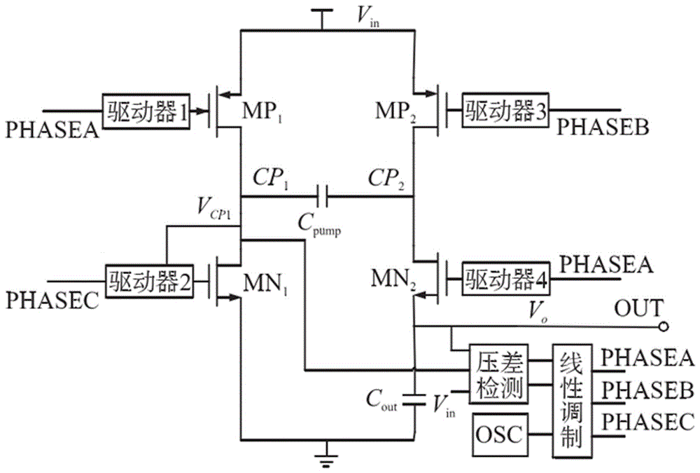
[0019] Such as figure 1 , The switch tube in the new charge pump circuit adopts a new type of power MOSFET, and the input and output voltage range of the circuit reaches 13 V~45V. The driver completes the shift function of controlling brainwashing, and controls the on and off of the switch tube. A high-voltage differential detection circuit is designed in the circuit to detect the difference between the left plate voltage of the pump capacitor and the output voltage and the power supply voltage, and use the detection result as the input signal of the linear modulation circuit to generate a feedback signal. The driver 2 is a current control circuit, which controls the charging current of the MN1 tube and improves the starting efficiency of the circuit. Under the control of the feedback loop, the output voltage changes linearly with the input voltage, the output voltage i...


PUM


Abstract

A high-voltage charge pump circuit is suitable for the field of motors. The circuit is composed of a two-phase voltage doubler circuit, an output voltage differential detection circuit, a pump capacitor left plate voltage differential detection circuit, and a driver 2 circuit. The switching tube in the new charge pump circuit adopts a new power MOSFET, and the input and output voltage range of the circuit reaches 13 V ~ 45V. The driver completes the shift function of controlling the brainwashing, and controls the on and off of the switch tube. A high-voltage differential detection circuit is designed in the circuit to detect the difference between the left plate voltage of the pump capacitor and the output voltage and the power supply voltage, and the detection result is used as the input signal of the linear modulation circuit to generate a feedback signal. The circuit structure is compact, the charging and discharging process is stable, the output voltage changes linearly with the input voltage, and the voltage is stable and the ripple is low.

Description

Technical field [0001] The invention relates to a high-voltage charge pump circuit, which is suitable for the motor field. Background technique [0002] The charge pump based on switched capacitor technology is widely used in boost circuit modules in various chips due to its excellent characteristics of low cost, low electromagnetic interference and high power efficiency. The stepper motor drive chip mainly includes a control circuit, an H-bridge drive circuit and a power management module. Among them, the H-bridge gate drive voltage comes from the boost output voltage of the charge pump circuit in the power management module. The charge pump circuit converts the high voltage of the driver chip with a wide input range into a boost output voltage that is linearly related to the input voltage. A special feedback control loop needs to be designed in the charge pump to adjust and stabilize the output voltage. In different applications, the feedback detection circuit and feedback co...

Claims


Application Information

Patent Timeline
Patent Type & Authority Applications(China)
IPC IPC(8): H02M3/07H02M1/14
CPCH02M3/07H02M1/143
Inventor 许亚夫
Owner 许亚夫
Why Eureka
Try Eureka