Punch filling pile bottom cleaning method

A cast-in-place pile and bottom cleaning technology, applied in sheet pile wall, construction, infrastructure engineering, etc., can solve the problem that the gravel slag and gravel cannot be completely removed from the pile hole, the reinforcement cage cannot be installed, and the depth of the pile hole is insufficient. and other problems to achieve the effect of ensuring civilized construction, short cleaning time and shortening construction period

Active Publication Date: 2018-01-05
CHINA MCC20 GRP CORP
View PDF4 Cites 4 Cited by
  • Summary
  • Abstract
  • Description
  • Claims
  • Application Information

AI Technical Summary

Problems solved by technology

[0002] In the construction of cast-in-place piles, especially punched-in-situ piles, due to the characteristics that the pile ends of this type need to penetrate into the rock (into the bearing layer), a large-weight hammer is used to impact the rock when forming the hole to crush and grind the rock into small pieces. In this process, a large amount of gravel residue will be produced. Most of these sediment can be replaced out of the pile hole by using the slag bucket and pouring new slurry, but the smaller gravel residue and gravel chips cannot be completely removed. The pile hole will cause insufficient pile hole depth, the reinforcement cage cannot be installed to the design depth, and the pile body will settle later due to excessive sedimentation.
[0003] There is a multifunctional drilling rig on the market, which can use gas lift positive circulation or gas lift reverse circulation, and use compressed air or high-pressure water to take the sediment at the bottom of the pile hole out of the pile hole through the pipe inside the drill pipe, but such a machine The equipment price is in the millions, and the construction cost is quite high

Method used


Image

  • Punch filling pile bottom cleaning method

Examples


Embodiment Construction

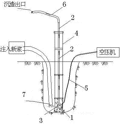
[0016] Such as figure 1 Shown is a method for clearing the bottom of a punching cast-in-situ pile, which includes: taking a section of concrete pouring conduit and welding a section of 20-25mm diameter elbow respectively on the inside and outside, and the two elbows are connected as the bottom section conduit 1;

[0017] Take a steel pipe 2 with a diameter of 50-80mm, weld a circular metal cover 3 at the end, the outer diameter of the metal cover is slightly smaller than the inner diameter of the concrete pouring conduit;

[0018] In addition, weld a steel plate on the top of a section of concrete pouring conduit, seal the top of the conduit, and open a hole at the top of the steel plate, the diameter of the hole is the same as that of the steel pipe in step 2, as the first section of conduit 4.

[0019] Install the conduit, after the cast-in-place pile has completed the pile hole, connect the hose 5 (the hose is connected to the air compressor) to the ventilating elbow of the...


PUM


Abstract

The invention relates to pile foundation construction, and discloses a punch filling pile bottom cleaning method. The method comprises the steps that two sections of connected bent pipes are welded tothe interior and the exterior of a section of concrete pouring guide pipe correspondingly to form a bottom section guide pipe; a circular horn mouth metal cover is welded to the end of a steel pipe,another section of concrete pouring guide pipe is taken, a steel plate is welded to the top of the section of concrete pouring guide pipe, a hole is formed after sealing, and the section of concrete pouring guide pipe is used as a first section guide pipe; after pile hole completion, a hose is connected to the ventilation bent pipes of the bottom section guide pipe and stretched to an air compressor, and the bottom section guide pipe is connected with a standard guide pipe to be installed into a filling pile hole; the steel pipe is installed into the concrete pouring guide pipe to the bottom of the hole; the first section guide pipe is installed to the portion, in the pile hole, of the guide pipe, and the steel pipe in the pipe just penetrates through the hole in the top of the first section guide pipe, and a hose is connected to the top of the steel pipe and stretched into a slag discharge pool; a new pulp pipe is directly connected into the bottom of the pile hole, new pulp is injected, the air compressor is started to increase pressure and refill air to push sediment and chippings at the bottom of the hole into the portion, with the metal cover, of the steel pipe, and the sediment and the chippings are pressed out of the pile hole along with the steel pipe. The sedimentation at the bottom of the hole can be thoroughly removed.

Description

technical field [0001] The invention relates to pile foundation construction, in particular to a construction method for cast-in-situ piles. Background technique [0002] In the construction of cast-in-place piles, especially punched-in-situ piles, due to the characteristics that the pile ends of this type need to penetrate into the rock (into the bearing layer), a large-weight hammer is used to impact the rock when forming the hole to crush and grind the rock into small pieces. In this process, a large amount of gravel residue will be produced. Most of these sediment can be replaced out of the pile hole by using the slag bucket and pouring new slurry, but the smaller gravel residue and gravel chips cannot be completely removed. The pile hole will cause insufficient pile hole depth, the reinforcement cage cannot be installed to the design depth, and the pile body will settle later due to too thick sediment. [0003] There is a multifunctional drilling rig on the market, whi...

Claims


Application Information

Patent Timeline
Patent Type & Authority Applications(China)
IPC IPC(8): E02D13/08
Inventor 施群凯
Owner CHINA MCC20 GRP CORP
Why Eureka
Try Eureka