Air preheating device utilizing boiler flue gas for heat exchanging

A technology for boiler flue gas and air preheating, applied in lighting and heating equipment, combustion methods, indirect carbon dioxide emission reduction, etc. To achieve the effect of reducing flue gas temperature, preventing thermal pollution, and good heat exchange effect

Inactive Publication Date: 2018-01-05
HARBIN JINJING BOILER
View PDF0 Cites 4 Cited by
  • Summary
  • Abstract
  • Description
  • Claims
  • Application Information

AI Technical Summary

Problems solved by technology

[0002] In the traditional structure, the combustion-supporting air of various boilers directly absorbs the cold wind from the outside, which is not conducive to combustion and consumes a certain amount of heat energy. To achieve the effect

Method used


Image

  • Air preheating device utilizing boiler flue gas for heat exchanging

Examples


Embodiment 1

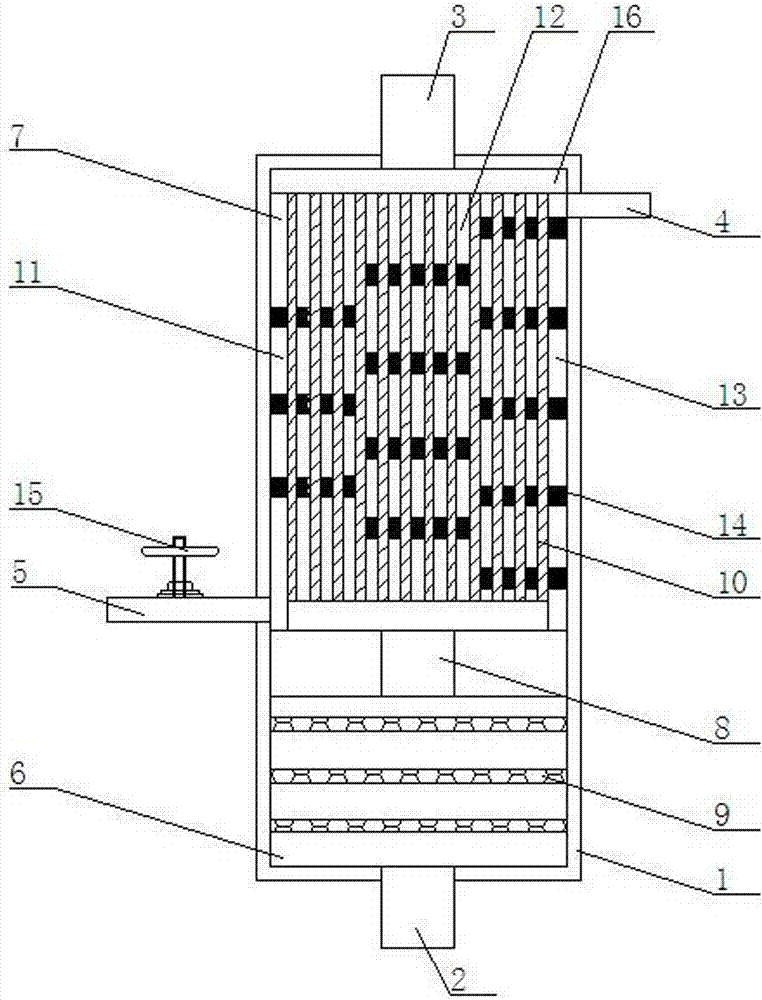
[0017] Such as figure 1 As shown, an air preheating device using boiler flue gas heat exchange includes a filter heat exchange tube 1, a flue gas inlet pipe 2, a flue gas outlet pipe 3, an air inlet pipe 4, and an air exhaust pipe 5. The bottom of the filter heat exchange cylinder 1 is equipped with a flue gas inlet pipe 2 in the middle, a flue gas exhaust pipe at the top of the middle device is installed, an air inlet pipe 4 is installed at the upper right end, and an air exhaust pipe 5 is installed at the lower left end; the inside of the filter heat exchange cylinder 1 It is composed of a smoke collecting filter chamber 6 and a heat exchange chamber 7. The smoke collecting filter chamber 6 is installed at the lower end of the filter heat exchange tube 1, and the heat exchange chamber 7 is installed at the upper end of the filter heat exchange tube 1. The top end of the filter chamber 6 is connected to the heat exchange chamber 7 through the air pipe 8; the bottom end of the ...

Embodiment 2

[0019] Such as figure 1 As shown, the inside of the smoke collecting filter chamber 6 is equipped with three layers of stainless steel metal filter screens 9 up and down.

Embodiment 3

[0021] Such as figure 1 As shown, the heat exchange chamber 7 is equipped with multiple rows of heat exchange tubes 10, which are composed of a left heat exchange tube area 11, a middle heat exchange tube area 12, and a right heat exchange tube area 13; the left heat exchange tube area 11 consists of top-to-bottom devices Three metal partition plates 14 with multiple heat exchange tube perforations are interspersed on the heat exchange tube 10 inside the left heat exchange zone; the middle heat exchange tube zone 12 is arranged from top to bottom with four heat exchange tubes. The perforated metal partition plate 14 of the heat pipe is interspersed on the heat exchange tube 10 inside the middle heat exchange zone; the right heat exchange tube zone 13 is separated from top to bottom by five pieces of metal with multiple heat exchange tube perforations The plate 14 is inserted on the heat exchange tube 10 inside the right heat exchange zone.


PUM


Abstract

An air preheating device utilizing boiler flue gas for heat exchanging comprises a filtering heat exchanging barrel, a flue gas inflow pipe, a flue gas exhausting pipe, an air inflow pipe and an air exhausting pipe; the flue gas inflow pipe is arranged on the middle of the bottom end of the filtering heat exchanging barrel; the flue gas exhausting pipe is arranged on the middle of the top end of the filtering heat exchanging barrel; the air inflow pipe is arranged at the upper right end of the filtering heat exchanging barrel; the air exhausting pipe is arranged at the lower left end of the filtering heat exchanging barrel; the interior of the filtering heat exchanging barrel is composed of a smoke collecting filtering chamber and a heat exchanging chamber; the smoke collecting filtering chamber is arranged at the lower end in the filtering heat exchanging barrel; the heat exchanging chamber is arranged at the upper end in the filtering heat exchanging barrel; the top end of the smokecollecting filtering chamber is connected with the heat exchanging chamber through a gas conveying pipe; the middle of the bottom end of the smoke collecting filtering chamber is connected with the flue gas inflow pipe; the middle of the top end of the heat exchanging chamber is connected with the flue gas exhausting pipe; the upper right end of the heat exchanging chamber is connected with the air flow pipe; and the lower left end of the heat exchanging chamber is connected with the air exhausting pipe. The air preheating device utilizing the boiler flue gas for heat exchanging can effectively utilize the boiler flue gas to preheat cold air, and it is facilitated that after the air enters a boiler, fuel can be combusted more sufficiently.

Description

Technical field [0001] The invention relates to an air preheating device, in particular to an air preheating device using boiler flue gas to exchange heat. Background technique [0002] In the traditional structure, the combustion-assisting air of various boilers directly absorbs the cold air from the outside, which is not conducive to combustion, and also consumes a certain amount of heat energy. Especially when low-calorific value fuels are used, the furnace temperature cannot meet the requirements for use. To achieve the effect of energy saving, and boiler flue gas generally contains a lot of heat energy, and for this heat energy, if it is not used, it will be a lot of waste, and the heat in the boiler flue gas will also cause thermal pollution to the air. . Summary of the invention [0003] The purpose of the present invention is to provide an air preheating device that uses boiler flue gas to exchange heat, which can effectively use boiler flue gas to preheat and heat cold...

Claims


Application Information

Patent Timeline
IPC IPC(8): F23L15/02F23J15/00F23J15/02F23J15/06
CPCY02E20/34
Inventor 谷哲学
Owner HARBIN JINJING BOILER
Why Eureka
Try Eureka