Connector heads, connector housings, connection systems, light source units and endoscopes
A technology for connectors and endoscopes, applied in the field of endoscopes, can solve the problems of non-compliance of electromagnetic compatibility, reduce system security, complicated connection operations, etc., achieve waterproof and light transmission, simple and easy operation, and Quasi-precise effect
- Summary
- Abstract
- Description
- Claims
- Application Information
AI Technical Summary
Problems solved by technology
Method used
Image
Examples
example 1
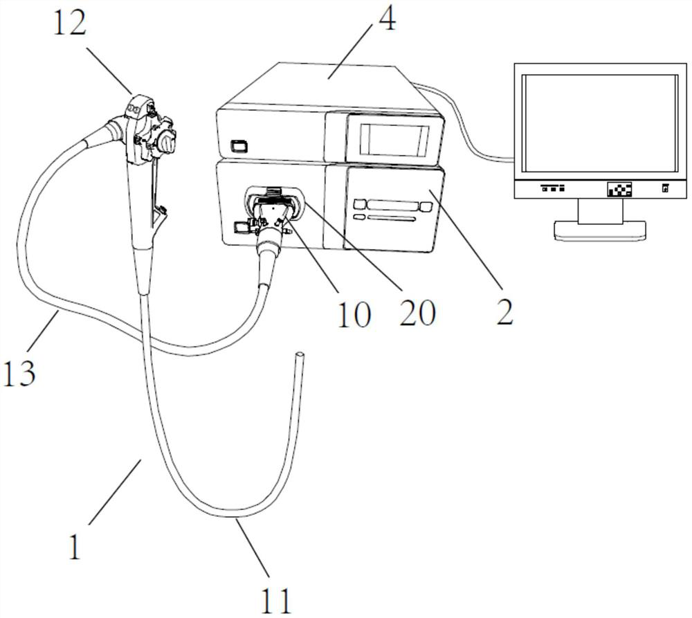
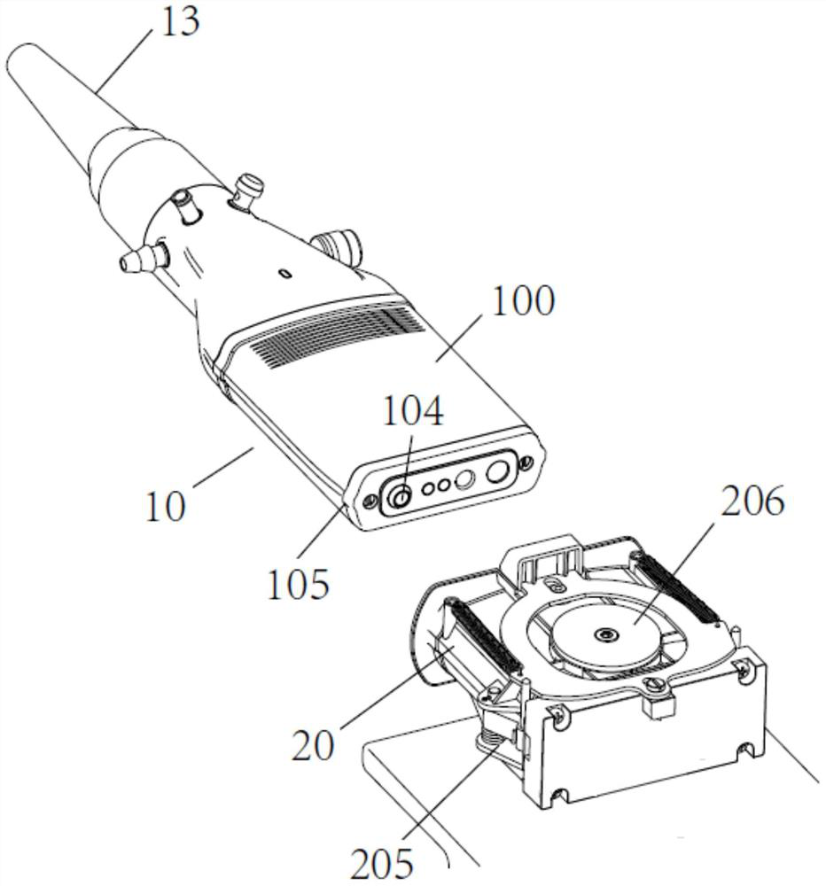
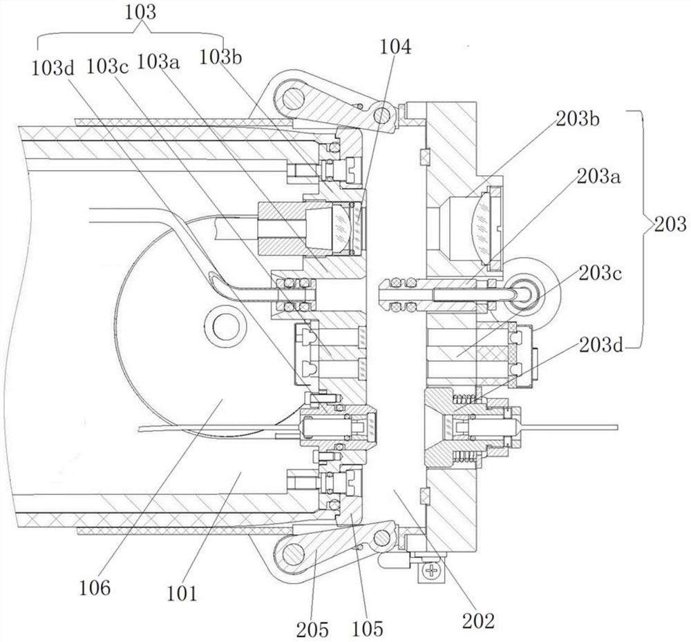
[0051] This example provides a connector header such as Figure 2-4 As shown, the endoscope connector head 10 is flat as a whole and has an oblong cross section. Structurally, the endoscope connector head 10 has a connector housing 100 and a receiving cavity 101 formed inside the connector housing.
[0052] The accommodating cavity 101 is formed along the connection direction (or insertion direction) of the connector head 10 and the connector base 20 . The rear end of the accommodating cavity 101 is communicated with the universal cable 13 , and the interior of the accommodating cavity 101 accommodates a plurality of connecting elements 102 extending from the universal cable 13 . These connecting elements 102 include, but are not limited to, a laser optical fiber 102d for transmitting image signals, an infrared optical fiber 102c for transmitting control and receiving signals, an illumination optical fiber 102b, and an air supply and water supply pipeline 102a.
[0053] At t...
example 2
[0067] Example 2 connector base
[0068] like Figure 3-5 As shown, this example provides a connector receptacle 20 that mates with the connector head 10 of Example 1. The connector base 20 may be provided on the light source device 2, but may not be limited thereto, for example, it may be provided on the image light source integrated machine.
[0069] The connector housing 20 mainly includes a connector housing housing 201 and a receiving cavity 202 defined by the connector housing housing 201 in structure.
[0070] The receiving cavity 202 corresponds to the connector head 10 , the cross section is an oval corresponding to the connector head 10 , and the size is just enough to accommodate the insertion of the main body of the connector head 10 .
[0071] The receiving cavity 202 accommodates a plurality of docking channels 203, each docking channel 203 accommodates a corresponding docking element 204, and each docking channel 203 corresponds to the connecting channel 103 o...
example 3
[0093] This example provides a wireless power supply system for supplying power to an endoscope. Different from the existing power supply system, the power supply system adopts a one-touch connection and does not expose any electrical connection points, so it does not need to be cleaned during cleaning. Waterproof treatment.
[0094] The power supply system includes a charging coil 106 disposed on the cavity wall of the receiving cavity 101 in the connector head 10 (see image 3 ) and the power supply coil 207 provided on the connector housing 201 (see Figure 5 ).
[0095] The charging coil 106 located in the connector head 10 is connected to the circuit board of the endoscope operating part.
[0096] Specifically, the power supply coil 207 located on the connector housing housing 201 is located at a position corresponding to the charging coil in the receiving cavity 101 . And the power supply coil 207 is electrically connected to the power supply circuit of the light sour...
PUM
 Abstract
Description
Claims
Application Information
 - R&D
- Intellectual Property
- Life Sciences
- Materials
- Tech Scout
- Unparalleled Data Quality
- Higher Quality Content
- 60% Fewer Hallucinations
Browse by: Latest US Patents, China's latest patents, Technical Efficacy Thesaurus, Application Domain, Technology Topic, Popular Technical Reports.
© 2025 PatSnap. All rights reserved.Legal|Privacy policy|Modern Slavery Act Transparency Statement|Sitemap|About US| Contact US: help@patsnap.com


