Antenna and communication base station employing same

An antenna and body technology, applied in the field of communication equipment, can solve the problems affecting the normal operation of communication base stations, the number of antennas cannot be increased, and the wind pressure index is unqualified, so as to protect the structure of the antenna itself, enhance the radiation range and accuracy, and be highly applicable range effect

Pending Publication Date: 2018-01-05
ZHEJIANG NINGYUAN COUNTY TOWER MAST MAKE
View PDF6 Cites 6 Cited by
  • Summary
  • Abstract
  • Description
  • Claims
  • Application Information

AI Technical Summary

Problems solved by technology

The iron tower is also called the communication base station. At present, the transformation of the conventional communication base station mainly includes solutions such as replacing the main material, replacing the iron tower, and relocating the iron tower. The construction industry of communication base stations has brought great challenges
[0003] In the process of three-network transformation of existing towers, there are a large number of single-operator towers that are unqualified due to wind pressure indicators, resulting in the existing towers being unable to increase the number of antennas 7, because disconnection will greatly affect people's daily life and work, so It is also not possible to rebuild towers, such as figure 1 As shown, the communication base station includes a pole on which two parallel arms 2 are arranged up and down, and the antenna body 3 is fixedly connected between the arms 2. The antenna body 3 on the communication base station is usually flat, and the communication base station The height of the antenna is basically controlled at more than 30 meters. The antenna body 3 is installed at a position close to the top of the communication base station, and the high-altitude wind force is relatively large. The antenna body 3 with a plate-like structure will withstand a relatively large wind force at high altitude. One, It will damage the antenna body 3 itself, causing the structure to be destroyed and cannot be used normally. Second, because the diameter of the column 1 of the communication base station is higher, the diameter is smaller. Sometimes, it will affect the entire communication base station and cause its own tilt, which will affect the normal operation of the communication base station

Method used


Image

  • Antenna and communication base station employing same
  • Antenna and communication base station employing same
  • Antenna and communication base station employing same

Examples


Embodiment 1

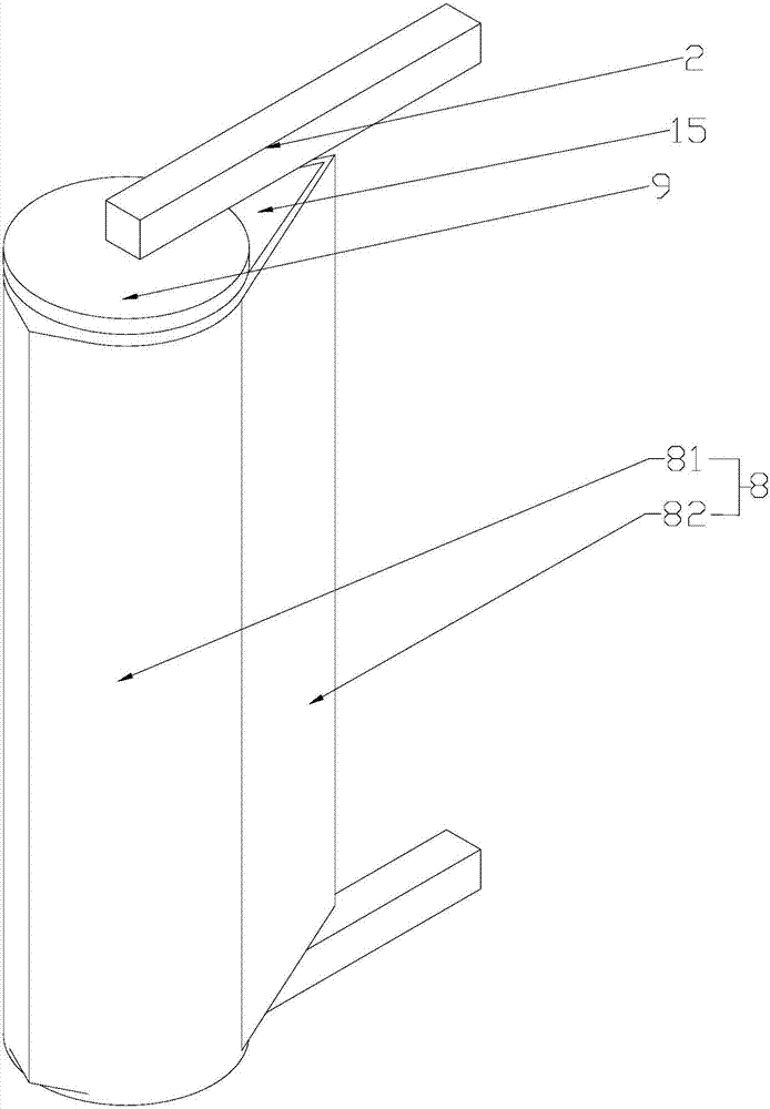
[0041] Such as image 3 , Figure 4 As shown, an antenna 7 includes an antenna body 3, the antenna body 3 is in the shape of a rectangular flat plate, and the support arm 2 is connected to the middle position of the two ends of the antenna body 3 along its own length direction, the support arm 2 is a rod-shaped structure, and the support arm 2. It is used to connect the column 1 of the communication base station. The two arms 2 are parallel to each other and perpendicular to the antenna body 3. There is a hollow body 8 on the outside of the antenna body 3. The hollow body 8 is a columnar structure. Openings are provided at both ends of the cavity body 8, the cross section of the cavity body 8 is drop-shaped, the antenna body 3 stands upright in the cavity body 8, the length of the antenna body 3 is less than the height of the cavity body 8, and the height difference between the two is 2 cm.

[0042] Such as image 3 , Figure 4As shown, the front end of the drop-shaped cav...

Embodiment 2

[0045] Such as Figure 6 to Figure 7 As shown, the difference from Embodiment 1 is that the connectors are different, and the objects that keep rotating also have certain differences. In Embodiment 2, there is no straight rod 11 and bearing end cover 9; the cavity body 8 is connected to the antenna through the connector On the main body 3, the connector is a circular plate 12. There are two circular plates 12, which are respectively located in the openings at both ends of the cavity body 8. The two circular plates 12 are kept parallel and coaxial up and down. The outer wall is embedded in the opening to form a conflicting connection with the side wall of the cavity body 8. A cover plate 15 is also provided in the opening. The cover plate 15 is integrally formed with the connecting plate to close the opening and protect the antenna body 3. . Such as Figure 8 As shown, a second bearing 14 is embedded in the end of the support arm 2 close to the antenna body 3, and a strut 13 ...

Embodiment 3

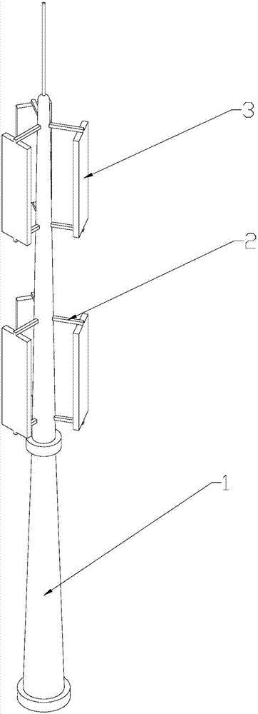
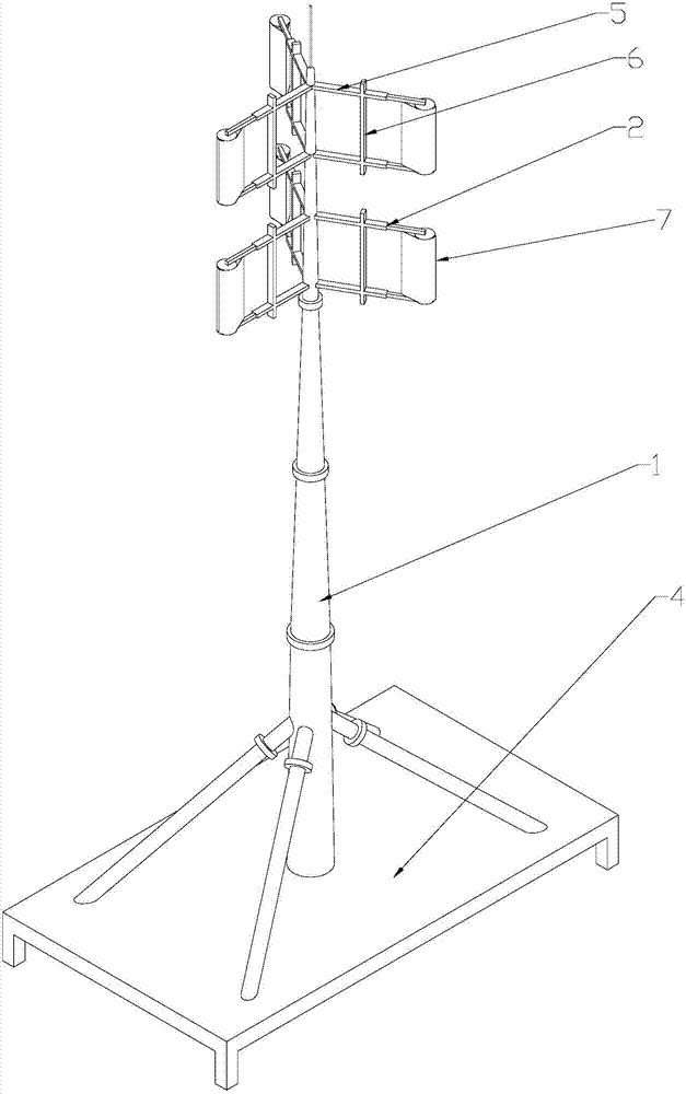
[0048] Such as figure 2 , Figure 5 As shown, a communication base station includes a base 4, and a column 1 is vertically fixed in the middle of the base 4. The communication base station also includes the above-mentioned antenna 7, and two parallel antennas are connected to the position near the tip of the column 1. Mounting rod 5, the mounting rod 5 is set up and down and is kept perpendicular to the column 1, and the holding rod 6 is connected between the two mounting rods 5 to form a mounting frame, the holding rod 6 and the column 1 are kept parallel, and the above-mentioned support arm 2 is fixed The holding pole 6, the support arm 2 and the holding pole 6 are kept vertical, and the installation frame evenly surrounds the column 1 around.


PUM


Abstract

The present invention discloses an antenna. The antenna comprises an antenna body and support arms configured to connect with two ends of the antenna body. Wind screen panels with arc-shaped surfacesand guidance top ends configured to guide a wind direction are arranged at the external portion of the antenna body, a cylindrical cavity body is encircled by the wind screen panels and the guidance top ends, the antenna body is located in the cavity body, connection pieces are arranged between the cavity body and the antenna body or the support arms and are configured to perform connection between the cavity body and the antenna body or the support arms, and the cavity body is vertically arranged and perform fixed-axis rotation motion around an axis itself. The antenna is simple in structureand convenient to install and regulate, greatly reduces a wind resistance coefficient, reduces stress in the antenna, facilitates protection of the structure of the antenna, and is long in service life; and the antenna has rain-proof, dustproof, thermal-insulation and heat-retaining performances, can perform normal working in a rugged environment, and has a wide application range. A single antennais small in stress, a communication base station employing the antenna can arrange a plurality of antennas, and therefore, radiation range and precision of the communication base station is enhanced.

Description

technical field [0001] The invention relates to the field of communication equipment, more specifically, it relates to an antenna and a communication base station using the antenna. Background technique [0002] With the establishment and development of the China Tower Company, the process of integrating the three networks into one has been greatly accelerated. With this process, the transformation of existing towers has also been put on the agenda. The iron tower is also called the communication base station. At present, the transformation of the conventional communication base station mainly includes solutions such as replacing the main material, replacing the iron tower, and relocating the iron tower. However, these solutions have a certain construction period and more transformation costs. The construction industry of communication base stations has brought great challenges. [0003] In the process of three-network transformation of existing towers, there are a large nu...

Claims


Application Information

Patent Timeline
Patent Type & Authority Applications(China)
IPC IPC(8): H01Q1/42H01Q1/24H04W88/08
Inventor 杜文甫霍同流邱裕忠
Owner ZHEJIANG NINGYUAN COUNTY TOWER MAST MAKE
Why Eureka
Try Eureka