A steel plate cutting device

A steel plate and cutting machine technology, applied in the direction of sawing machine, sawing machine tool, metal sawing equipment, etc., can solve the problems of easy displacement and affecting the cutting quality of steel plate remaining materials, and achieve the effect of simple structure

Active Publication Date: 2019-03-08
重庆纵翼机械制造有限公司
View PDF5 Cites 0 Cited by
  • Summary
  • Abstract
  • Description
  • Claims
  • Application Information

AI Technical Summary

Problems solved by technology

[0004] The purpose of the present invention is to provide a steel plate cutting machine, which is used to solve the problem that when cutting the remaining steel plate, the remaining material used for clamping is too short and easily shifted under force, which affects the cutting quality of the remaining steel plate

Method used


Image

  • A steel plate cutting device
  • A steel plate cutting device
  • A steel plate cutting device

Examples


Embodiment Construction

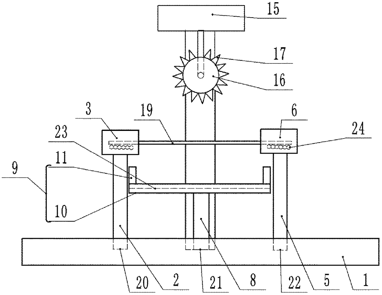
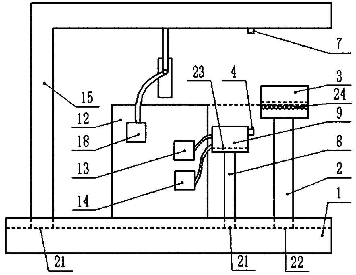
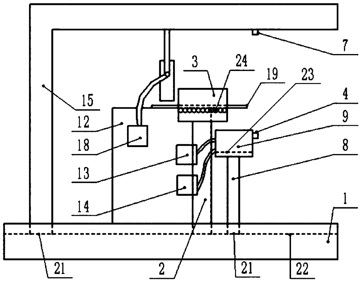
[0022] The reference numerals in the accompanying drawings of the description include: base 1, first telescopic rod 2, first clamp transmission device 3, infrared emitter 4, second telescopic rod 5, second clamp transmission device 6, infrared receiver 7, The third telescopic rod 8, splint 9, bottom plate 10, splint arm 11, cutting table 12, hot melt glue box 13, air-conditioning box 14, L-shaped arm bar 15, cutting knife 16, cutting knife teeth 17, hot air box 18, steel plate 19. The first chute 20 , the second chute 21 , the third chute 22 , the fourth chute 23 , and the roller set 24 .

[0023] Such as figure 1 As shown, a steel plate cutting machine includes a base 1, and the base 1 is provided with three chutes from left to right, namely the first chute 20, the second chute 21 and the third chute 22, the second chute Install the L-shaped arm bar 15 and the third telescopic link 8 on the slot 21. The L-shaped arm bar 15 transverse arm and the vertical arm are all adjustab...


PUM


Abstract

The invention relates to the technical field of cutting machine devices, in particular to a steel plate cutting device. The steel plate cutting device comprises a base, the base is sequentially provided with an L-shaped arm rod, a clamping plate and a cutting table fixedly infrared receiver between the L-shaped arm rod and the clamping plate, and oppositely-arranged clamping and transferring devices are connected to the positions, on the two sides of the L-shaped arm rod, a cutting table and the clamping plate, of the base in a sliding manner; a cutting knife is rotationally connected to a transverse arm of the L-shaped arm rod, is externally connected with a hot air box and is provided with a hole; the clamping plate comprises a clamping plate base plate and two clamping plate arms arranged on the base plate, the clamping plate base plate and the clamping plate arms are each provided with cold air holes and hot melt adhesive holes, the cold air holes are externally connected with a cold air box, and the hot melt adhesive holes are externally connected with a hot melt adhesive box; an infrared transmitter is arranged at the end, far away from the cutting table, of the clamping plate, and an infrared receiver is arranged on the L-shaped arm rod in a manner of corresponding to the infrared transmitter; and the two clamping and transferring devices are oppositely provided with grooves, and roller sets are arranged at the groove bottoms. By means of the technical scheme, the length of a remaining material can be increased, and influences of displacement of the clamped remainingmaterial during cutting on the cutting effect are prevented.

Description

technical field [0001] The invention relates to the technical field of cutting machine devices, in particular to a steel plate cutting machine. Background technique [0002] In steel production enterprises, it is necessary to cut and blank raw materials, and cut steel plates to meet the required specifications and sizes. The existing steel plate cutting machine has a simple structure, the steel plate is transferred to the cutting table, the clamping mechanism clamps the steel plate, and the cutting knife cuts the steel plate. [0003] When cutting the steel plate in the last section, the steel plate is subjected to a huge cutting force of the cutting knife, the remaining material used for clamping is shorter than when cutting the steel plate before, the area of ​​the remaining material clamped by the clamping mechanism is less, and the friction between the clamping mechanism and the remaining material The force is small, and it cannot overcome the huge cutting force when cu...

Claims


Application Information

Patent Timeline
Patent Type & Authority Patents(China)
IPC IPC(8): B23D45/00B23D61/02
Inventor 蒋儒章
Owner 重庆纵翼机械制造有限公司
Why Eureka
Try Eureka