Bridge girder erection machine used for erecting precast beams and bridge girder erection method thereof

A technology of bridge erecting machine and prefabricated beams, which is applied in the direction of erecting/assembling bridges, bridges, bridge construction, etc., which can solve the problems affecting the force of bridge erection, affecting construction efficiency, and greatly affecting the natural environment, so as to reduce the cost of the site environment Requirements, low overall project cost, and good product quality control

Pending Publication Date: 2018-01-09
ZHENGZHOU NEW DAFANG HEAVY IND & TECH
View PDF6 Cites 1 Cited by
  • Summary
  • Abstract
  • Description
  • Claims
  • Application Information

AI Technical Summary

Problems solved by technology

[0004] 1. Existing bridge pier columns and cover beams are generally installed on-site by hoisting and binding steel bars, on-site installation of formwork, and on-site pouring and maintenance. The construction is greatly affected by the natural environment, quality control is difficult, and the surrounding environment is seriously polluted
[0005] 2. The existing bridge erecting machines usually cannot realize reverse construction by themselves, and generally require the auxiliary disassembly and assembly of large-tonnage cranes, and even the disassembly and assembly of the whole machine can be realized;
[0006] 3. Many of the existing bridge erecting machines require

Method used


Image

  • Bridge girder erection machine used for erecting precast beams and bridge girder erection method thereof
  • Bridge girder erection machine used for erecting precast beams and bridge girder erection method thereof
  • Bridge girder erection machine used for erecting precast beams and bridge girder erection method thereof

Examples


Embodiment Construction

[0062] The present invention will be further described below in conjunction with the accompanying drawings.

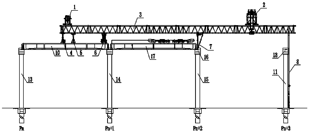
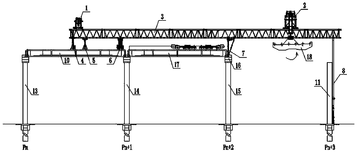
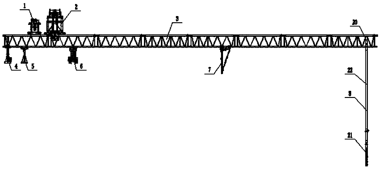
[0063] Such as figure 1 As shown, the bridge erecting machine used includes a machine arm 3 designed symmetrically in both the longitudinal direction and the transverse direction. The belonging machine arm 3 is a double box girder structure. 8. From top to bottom, it includes a connecting rod 20, a long support rod 22 and a bottom leg 21. The connecting rod 20 is detachably connected to the front end of the machine arm 3, and the lower end of the connecting rod 20 is detachably connected to the top of the long support rod 22. The lower end of the long support rod 22 is detachably connected with the bottom leg 21, a jacking mechanism is provided on the bottom leg 21, a top leg 4 is installed at the rear end of the machine arm 3, and a The front outrigger 7 and the rear outrigger 6 that can walk along the longitudinal direction, that is, the construction direction, are ...


PUM


Abstract

The invention discloses a bridge girder erection machine used for erecting precast beams and a bridge girder erection method thereof. The bridge girder erection machine comprises a mechanical arm which is symmetrically designed in the longitudinal direction and in the horizontal direction, and the mechanical arms are of a double-box-beam structure. A front assistant supporting leg is installed atthe front end of the mechanical arm, a jack-up supporting leg is arranged at the rear end of the mechanical arm, a front supporting leg and a rear supporting leg which are capable of walking in the longitudinal direction are arranged in the middle of the mechanical arm, and a bearing support leg is arranged on the rear side of the rear supporting leg. The method that bridge girder erection is erected by using the bridge girder erection machine is very suitable for quick erection of urban roads, urban light rails, subway routes and other overground overpasses in the peri-urban areas and the places where the construction conditions are complex, the traffic pressure of a construction environment is high; by means of the bridge girder erection machine and the bridge girder erection method, itwill be certain to drive the construction of elevated highways, the urban light rails and subway viaducts in Chinese to be developed to the environment-friendly, industrialized and standardized construction, and the economic and social benefits will be increasingly obvious.

Description

technical field [0001] The invention belongs to the technical field of prefabricated bridge construction, in particular to a bridge erecting machine and a bridge erecting method for erecting fully prefabricated beams. Background technique [0002] With the acceleration of the pace of urbanization in my country, in order to save land resources, there are more and more viaducts on the ground such as urban roads, urban light rail and subway lines. It is different from the previous viaducts in that most of these viaducts appear around the city, the construction conditions are complicated, and the traffic pressure in the construction environment is high, which puts forward higher requirements for the adaptability of the bridge erecting machine. [0003] The construction technology of the road bridge erecting machine commonly used at this stage is mature and widely used, but its shortcomings are becoming more and more obvious with the development of the working environment: [00...

Claims


Application Information

Patent Timeline
IPC IPC(8): E01D21/00
Inventor 张志华贾力锋陈德利代宇王琪程波陈媛媛陈永久牛青林李军超张俊艳白康宋飞宋鲁竞
Owner ZHENGZHOU NEW DAFANG HEAVY IND & TECH
Why Eureka
Try Eureka