

Fan-out packaging device
A packaging device, fan-out technology, applied in the direction of electric solid device, semiconductor device, semiconductor/solid state device parts, etc. Good thermal conductivity, improved packaging accuracy, and beneficial effects on heat dissipation
- Summary
- Abstract
- Description
- Claims
- Application Information
AI Technical Summary
Problems solved by technology
Method used
Image

Examples
Embodiment Construction
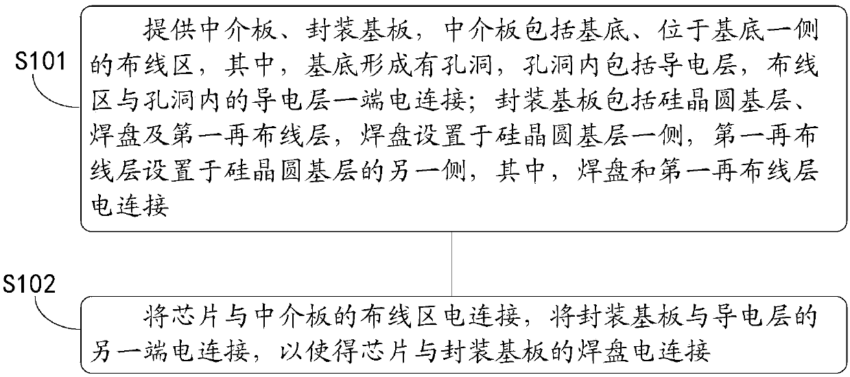
[0028] see figure 1 , figure 1 It is a schematic flow chart of an embodiment of the fan-out packaging method of the present invention, the method includes:
[0029] S101: Provide an interposer and a packaging substrate. The interposer includes a base and a wiring area on one side of the base, wherein the base is formed with a hole, the hole includes a conductive layer, and the wiring area is electrically connected to one end of the conductive layer in the hole; the packaging substrate includes The base layer of the silicon wafer, the pad and the first rewiring layer, the pad is arranged on one side of the base layer of the silicon wafer, and the first rewiring layer is arranged on the other side of the base layer of the silicon wafer, wherein the pad and the first rewiring layer layer electrical connection;
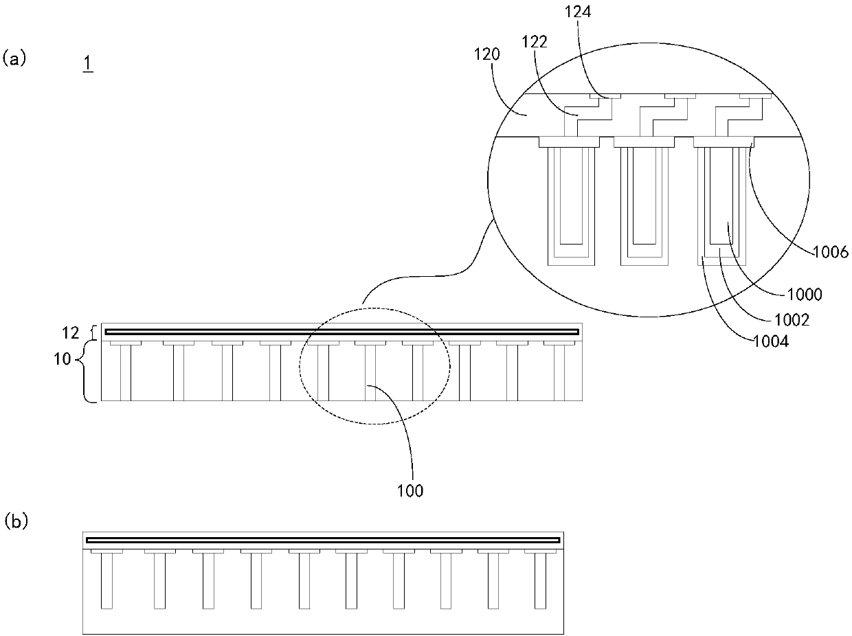
[0030] In an application scenario, such as figure 2 as shown, figure 2 for figure 1 A schematic structural diagram of an embodiment of an interposer. The interpos...
PUM
 Abstract
Description
Claims
Application Information