Electromagnetic casting system

A pouring system and electromagnetic technology, which is applied in the field of metal forming equipment, can solve the problems of refining and degassing in holding furnaces, porosity in castings, and affecting mechanical properties of castings.

Inactive Publication Date: 2018-01-12
北京北方恒利科技发展有限公司
View PDF11 Cites 2 Cited by
  • Summary
  • Abstract
  • Description
  • Claims
  • Application Information

AI Technical Summary

Problems solved by technology

[0003] Existing electromagnetic pouring equipment is prone to mold filling difficulties and insufficient pouring when pouring large and complex thin-walled parts, and it is almost always carried out in a conventional atmospheric environment (limited by the electromagnetic pouring system, it is impossible to carry

Method used


Image

  • Electromagnetic casting system
  • Electromagnetic casting system
  • Electromagnetic casting system

Examples


example 1

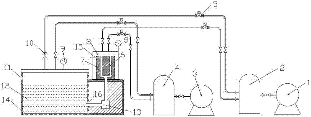
[0041] a. The molten metal enters the holding furnace from the sealed hatch on the left side of the holding furnace d, and the holding furnace starts to work; when the holding furnace maintains a constant temperature, turn on the vacuum pump to evacuate the holding furnace and the mold cavity at the same time.

[0042] b. When the vacuum degree reaches 0.01MPa, keep it for a certain period of time, so that the gas in the molten metal is completely extracted. At this time, both the holding furnace and the mold cavity are kept vacuum, and the vacuum degree on both sides is equal, which is conducive to smooth electromagnetic casting. filling.

[0043] c. Then start electromagnetic pouring, the current flowing in the metal flow will generate an induced magnetic field, which will be superimposed on the external magnetic field, so that the synthetic magnetic field will be unevenly distributed from the inlet to the outlet of the electromagnetic pump, and will flow with the liquid meta...

example 2

[0048] a. The molten metal enters the holding furnace from the sealed hatch on the left side of the holding furnace, and the holding furnace starts to work; when the holding furnace maintains a constant temperature, the vacuum pump is turned on to evacuate the holding furnace and the mold cavity at the same time.

[0049] b. When the vacuum degree reaches 0.01MPa, keep it for a certain period of time so that the gas in the molten metal is completely extracted. At this time, both the holding furnace and the mold cavity are kept vacuum, and the vacuum degree on both sides is equal, which is beneficial to electromagnetic pouring Smooth filling.

[0050] c. Then start electromagnetic pouring, the current flowing in the liquid metal will generate an induced magnetic field, which will be superimposed on the external magnetic field, so that the synthetic magnetic field will be unevenly distributed from the inlet to the outlet of the electromagnetic pump, and will flow with the liquid ...


PUM


Abstract

The invention belongs to the technical field of metal forming equipment, and particularly relates to an electromagnetic casting system. The system comprises a heat preservation device, an electromagnetic casting device, a vacuum device and a pressure device, wherein the heat preservation device comprises a heat preservation furnace; the electromagnetic casting device comprises a casting mold cavity; and the vacuum device and the pressure device are correspondingly connected with the heat preservation furnace and the casting mold cavity, and are used for carrying out vacuum pumping treatment and pressurization treatment on the heat preservation furnace and the casting mold cavity correspondingly. According to the electromagnetic casting system, on the basis of electromagnetic casting, the vacuum pumping treatment is carried on metal liquid contained in the heat preservation furnace and pressure is slowly applied to the metal liquid during casting, and the vacuum pumping treatment and pressurization operation are also carried out in a casting mold region, thus the phenomenon of air holes generated during casting of the metal liquid is avoided, the quality of a casting piece is improved, the situations that mold filling of the metal liquid is complete and solidification is achieved according to a preset solidification process are guaranteed, and the service life of an electromagnetic pump is further prolonged.

Description

technical field [0001] The invention belongs to the technical field of metal forming equipment, in particular to an electromagnetic pouring system. Background technique [0002] Electromagnetic casting is a model-free continuous casting realized by the principle of electromagnetic induction, that is, relying on the electromagnetic force generated by the inductor fed with alternating current to overcome the static pressure and surface tension of liquid metal to achieve non-contact casting. The key to the success of electromagnetic casting is to stabilize the molten metal column and keep its height constant. [0003] Existing electromagnetic pouring equipment is prone to mold filling difficulties and insufficient pouring when pouring large and complex thin-walled parts, and it is almost always carried out in a conventional atmospheric environment (limited by the electromagnetic pouring system, refining and casting in the holding furnace cannot be carried out. Degassing treatm...

Claims


Application Information

Patent Timeline
IPC IPC(8): B22D27/02B22D27/13
Inventor 宋彬徐宏王明杰孙宁侯蔚
Owner 北京北方恒利科技发展有限公司
Why Eureka
Try Eureka