Welder control circuit system

A technology for controlling circuits and welding machines, applied in manufacturing tools, welding equipment, arc welding equipment, etc., can solve the problems that analog circuits cannot adapt to multi-functional operations and complex operations, and achieve diversified data transmission methods and long transmission distances Far, parameter display intuitive and clear effect

Pending Publication Date: 2018-01-12
YANCHENG DLD WELDING SCI & TECH
View PDF0 Cites 1 Cited by
  • Summary
  • Abstract
  • Description
  • Claims
  • Application Information

AI Technical Summary

Problems solved by technology

[0003] With the development of power electronics technology, control technology, microprocessor technology and welding technology, welding equipment is becoming more and more powerful, and the operation is becoming more and more complicated. Traditional analog circuits cannot adapt to multi-functional operations. Want to get better Human-computer interaction and more powerful functions must use intelligent control chips to control the welding machine

Method used


Image

  • Welder control circuit system
  • Welder control circuit system

Examples


Embodiment Construction

[0021] The present invention will be further described in detail below in conjunction with the accompanying drawings and specific embodiments.

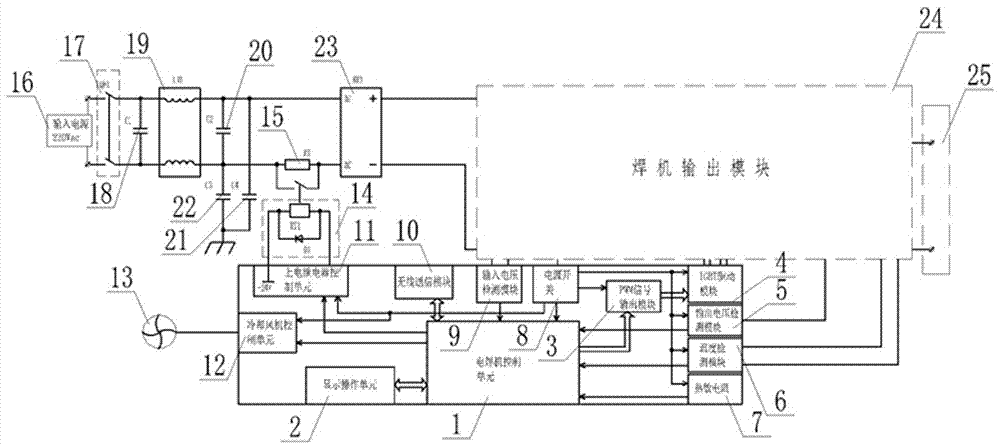
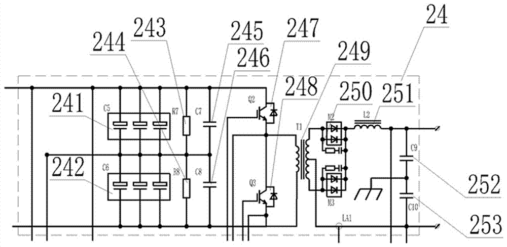
[0022] as attached figure 1 and figure 2 The shown welding machine control circuit system of the present invention includes a welding machine control unit 1, a display operation unit 2, a signal output module 3, an IGBT drive module 4, an output voltage detection module 5, a temperature detection module 6, a thermal Sensitive resistor 7, power switch 8, input voltage detection module 9, wireless communication module 10, power-on relay control unit 11, cooling fan control unit 12, fan 13, power-on relay 14, power-on resistor 15, input power supply 16, input Switch 17, input capacitor 18, filter 19, output capacitor 20, first ground capacitor 21, second ground capacitor 22, rectifier module 23, welder output module 24 and welder output 25, the electric welder controls The unit 1 is electrically connected with a display operation unit...


PUM


Abstract

The invention relates to a welder control circuit system which is mainly characterized in that a display operation unit and a signal output module are connected with a welder control unit; data information detected by an output voltage detection module, a temperature detection module, a thermistor and an input voltage detection module is transmitting to the welder control unit through lines; a wireless communication module is also connected onto the welder control unit, and used for sending and receiving communication data; a fan is connected to the output end of a cooling fan control unit through a line; a power-on relay and a power-on relay control unit are electrically connected with each other; and after an input power source passes through an input switch, an input end capacitor, a wave filter and an output end capacitor in sequence, two poles of the output end of the input power source are electrically connected with the ground through a first grounded capacitor and a second grounded capacitor correspondingly. The welder control circuit system provided by the invention has the advantages that the voltage application scope is wide, the display of state parameters is visual, and the safety is high.

Description

technical field [0001] The invention relates to the field of welding machine control equipment, in particular to a welding machine control circuit system. Background technique [0002] With the development of industry, electric welding machine has been widely used as an indispensable welding equipment in industrial production. MMA welding refers to a welding method in which the electrode in the electrode holder acts as the welding electrode, the arc burns between the electrode and the workpiece, and the electrode as the welding electrode shortens as the welding progresses. The electrode holder must be constantly moved towards the workpiece so that the distance between the electrode and the molten weld remains constant. MMA welding can be used in almost any condition, so it is a fairly common method in the welding industry. The IGBT inverter DC welding machine is a new type of arc welding power source. Its good electrical performance and remarkable energy-saving effect have...

Claims


Application Information

Patent Timeline
Patent Type & Authority Applications(China)
IPC IPC(8): B23K9/10
Inventor 董志文刘连华
Owner YANCHENG DLD WELDING SCI & TECH
Why Eureka
Try Eureka