Rapid clamping and precise positioning device and method thereof

A precise positioning, positioning and clamping technology, applied in positioning devices, workpiece clamping devices, auxiliary devices, etc., can solve problems such as difficulty in ensuring the relative positioning of the processing execution end, no instructions or reports found, and data not yet collected. The effect of reducing repositioning time, high repeat positioning accuracy and strong structural adaptability

Inactive Publication Date: 2018-01-12
SHANGHAI SPACE PRECISION MACHINERY RES INST
9 Cites 2 Cited by

AI-Extracted Technical Summary

Problems solved by technology

When the workpiece is a tubular workpiece, it is often difficult to ensure the relative positioning of the processing execution end and the workpiece in multiple clampings due to the lack of positioning design of the tubular workpiece itself
However, designing a high-precision positioning structure in the tubular workpiece...

Method used

The present invention installs the pipe fitting, that is, the tubular workpiece, on the workpiece clamping part 2 in the clamping and positioning device provided by the invention, and tightens the locking bolt so that the clamping, positioning device and the pipe fitting become a fixed Workpiece tooling combination. When this clamping and positioning device is needed in the process, the zero point positioning pin 5 on the tooling and the zero point positioning female end of the processing execution end (for example, the manipulator) cooperate with the workpiece tooling combination described in the clamping to complete the relevant processing or assembly work . When the workpiece tooling combination is remo...

Abstract

The invention provides a rapid clamping and precise positioning device. The rapid clamping and precise positioning device comprises a positioning and clamping part (1), a workpiece clamping part (2) and a connecting mechanism. The positioning and clamping part (1) comprises a zero point positioning pin (5), and has a rapid, repeated and precise positioning function; and the workpiece clamping part(2) comprises two flaps of open-close type clamping pieces, and the tightening degree is adjusted through a rotary knob. According to a method of the rapid clamping and precise positioning device, repeated and rapid clamping and precise positioning of a thin-walled bent pipe are achieved, the clamping and dismounting efficiency is high, the response speed is high, and the repeated positioning precision is high; and automatic positioning and rapid and repeated clamping can be achieved under the effect of a mechanical arm, the structural adaptability is high, and rapid and repeated clamping andhigh-precision repeated positioning of the thin-walled bent pipe are achieved.

Application Domain

Welding/cutting auxillary devicesWork holders +5

Technology Topic

Thin walledBiomedical engineering +1

Image

  • Rapid clamping and precise positioning device and method thereof
  • Rapid clamping and precise positioning device and method thereof
  • Rapid clamping and precise positioning device and method thereof

Examples

  • Experimental program(1)

Example Embodiment

[0066] The present invention will be described in detail below in conjunction with specific embodiments. The following examples will help those skilled in the art to further understand the present invention, but do not limit the present invention in any form. It should be pointed out that for those of ordinary skill in the art, several changes and improvements can be made without departing from the concept of the present invention. These all belong to the protection scope of the present invention.
[0067] In the description of the present invention, it should be understood that the terms "upper", "lower", "front", "rear", "left", "right", "vertical", "horizontal", "top", The orientation or positional relationship indicated by "bottom", "inner", "outer", etc. are based on the orientation or positional relationship shown in the drawings, which is only for the convenience of describing the present invention and simplifying the description, and does not indicate or imply the pointed device Or the element must have a specific orientation, be constructed and operated in a specific orientation, and therefore cannot be understood as a limitation of the present invention.
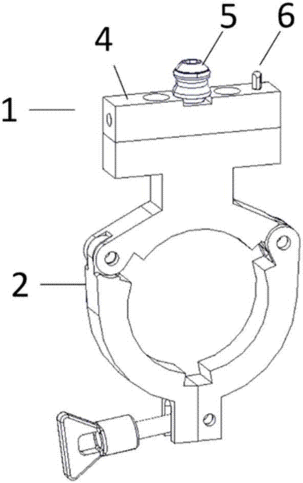
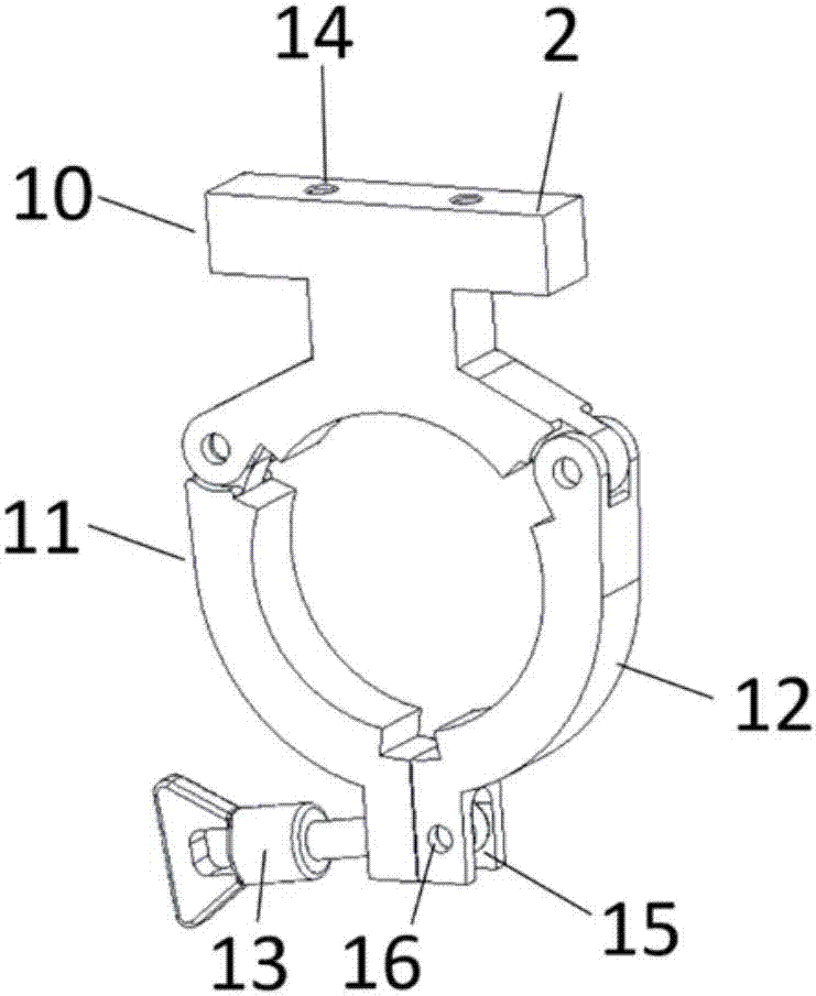
[0068] The present invention provides a quick clamping and precise positioning device, which includes a connecting mechanism, a positioning clamping component 1, a workpiece clamping component 2; the positioning clamping component 1, the workpiece clamping component 2 are firmly connected by the connecting mechanism; The workpiece clamping component 2 includes a transition piece 10, a first clamping piece 11, and a second clamping piece 12; the first clamping piece 11 and the second clamping piece 12 are respectively located on the left and right sides of the transition piece 10. One end of the transition piece 10 is tightly connected to the positioning and clamping component 1; the other end of the transition piece 10 is tightly connected to the first clamping piece 11 and the second clamping piece 12.
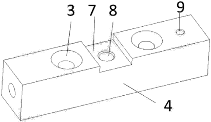
[0069] The connecting mechanism includes a first fastener 3; the positioning and clamping component 1 is firmly connected to the workpiece clamping component 2 through the first fastener 3.
[0070] The two ends of the transition piece 10 respectively extend a first protruding end and a second protruding end along the length; the first protruding end is firmly connected to the positioning and clamping component 1; the second protruding end is connected to The first clamping member 11 and the second clamping member 12 are firmly connected; the first protruding end has a first mounting hole 14 for a first fastener; the first mounting hole 14 of the first fastener is connected to The matching of the first fastener 3 of the connecting mechanism enables the first protruding end to be firmly connected to the positioning and clamping component 1.
[0071] Both ends of the second protruding end respectively have a first clamping piece mounting portion and a second clamping piece mounting portion; the first clamping piece mounting portion matches the first clamping piece 11; the second The clamping piece mounting portion matches the second clamping piece 12; the first clamping piece mounting portion is movably connected to one end of the first clamping piece 11; the second clamping piece mounting portion is connected to the second clamping piece 11 One end of the piece 12 is movably connected; the other end of the first clamping piece 11 is movably connected with the other end of the second clamping piece 12.
[0072] The first protruding end, the second protruding end, the first clamping member 11, and the second clamping member 12 constitute a ring shape; the ring shape constitutes a workpiece clamping space; the first clamping member mounting portion Between the first clamping member 11 and one end of the first clamping member 11, between the second clamping member mounting portion and one end of the second clamping member 12, and between the other end of the first clamping member 11 and the second clamping member 12. There is a first groove; the first grooves all face the workpiece clamping space.
[0073] The workpiece clamping component 2 further includes an adjusting member 13; the other end of the first clamping member 11 and the other end of the second clamping member 12 are movably connected by the adjusting member 13; The other end and the other end of the second clamping member 12 both have a second groove 15; wherein the second groove 15 at the other end of the second clamping member 12 also has a through hole 16; One end is fixed on the other end of the second clamping member 12 through the connecting mechanism through the through hole 16; the other end of the adjusting member 13 has a knob; the knob is threadedly engaged with the other end of the adjusting member 13; There is a fastening position between the knob and the other end of the adjusting member 13; when the knob is rotated to the fastening position, the other end of the first clamping member 11 is closely connected with the other end of the second clamping member 12, Make the clamping space of the work piece closely fit the work piece, which is recorded as the clamping work piece mode; when the knob is rotated to not be in the tightening position, the other end of the first clamping piece 11 and the second clamping piece 12 Separation of the other end of the workpiece can separate the workpiece from the workpiece clamping space, which is recorded as the workpiece release mode; the circumference of the workpiece clamping space in the workpiece clamping mode is smaller than the workpiece clamping space in the workpiece clamping mode The perimeter.
[0074] The first protruding end is a hinged female connector; the second protruding end is a hinged male connector; one end of the first clamping member 11 is a hinged male connector matching the first protruding end ; One end of the second clamping member 12 is a hinged female head that matches the second protruding end.
[0075] The positioning and clamping component 1 includes a positioning block 4, a zero-point positioning pin 5 and a first pin 6; the positioning block 4 has a first fastener second corresponding to the position of the first fastener first mounting hole 14 Mounting hole; the first fastener 3 of the connecting mechanism penetrates through the first mounting hole 14 of the first fastener and the second mounting hole of the first fastener to make the positioning block 4 and the workpiece clamping member 2 The transition piece 10 is connected; there is a third groove between the second mounting holes of the first fastener; the third groove is an interference fit with the zero-point positioning pin 5; the zero-point positioning pin 5 is buckled in In the third groove, it is connected with the positioning block 4 through the zero-point positioning pin mounting hole 8 of the third groove; the positioning block 4 also has a first pin mounting hole 9; the first pin mounting hole is connected to the first The pins 6 match; the first pin 6 is connected to the positioning block 4 through the first pin mounting hole.
[0076] The present invention also provides a method for quick clamping and precise positioning, which includes the steps of clamping and positioning the workpiece by using the aforementioned quick clamping and precise positioning device.
[0077] It should be noted that the positioning and clamping component 1 is preferably a positioning and clamping component; the first fastener 3 is preferably a countersunk bolt; the workpiece mentioned in the present invention is preferably a pipe; the first clamping component 11 Preferably, it is located on the left side of the armor device provided by the present invention; the second clamping member 12 is preferably located on the right side of the armor device provided by the present invention; the second fastener 13 is preferably a locking bolt The first mounting hole 14 of the first fastener is preferably a bolt hole; the second groove 15 is preferably a U-shaped groove; the other end of the first protruding end is a hinged female connector, preferably Is an embedded hinged female connector; the other end of the second protruding end is a hinged male connector, preferably an embedded hinged male connector; one end of the first clamping member 11 is connected to the first protruding end A matching hinged male connector, preferably an embedded hinged male connector; one end of the second clamping member 12 is a hinged female connector matching the second protruding end, preferably an embedded hinged connector Female head; the first 6 is preferably a diamond-shaped pin; the through hole 16 is preferably a hinge hole; the first pin mounting hole 9 is preferably a diamond-shaped pin bolt hole; the zero-point positioning pin mounting hole 8 is preferably Zero-point positioning pin bolt hole; the other end of the first clamping member 11 is preferably a fastening pressure plate; the above-mentioned are preferred examples of the present invention, and should not constitute a limitation to the present invention.
[0078] The present invention is specifically a clamping and positioning device that is easy to disassemble and assemble, which is preferably applied to disassemble and disassemble tubular workpieces; it solves the problem of processing the execution end after repeated clamping, that is, the positioning problem between the manipulator and the tubular workpiece.
[0079] The working principle of the present invention will be further explained below:
[0080] The invention installs the pipe fitting, that is, the tubular workpiece, on the workpiece clamping part 2 of the clamping and positioning device provided by the invention, and tightens the locking bolts so that the clamping, positioning device and the pipe fitting become a fixed workpiece tooling assembly . When the clamping and positioning device is needed in the process, the zero-point positioning pin 5 on the tooling and the zero-point positioning female end of the processing execution end (for example, a manipulator) are used to clamp the workpiece tooling combination to complete the related processing or assembly work . When the workpiece tooling assembly is removed from the processing execution end, the workpiece tooling assembly is removed as a whole, and when it needs to be operated again, the workpiece tooling assembly can be installed again. In multiple clamping, the tubular workpiece and the tooling, that is, the clamping and positioning device are mechanically connected, and the relative position is fixed, and the tooling and the processing execution end are connected by a zero-point positioning system, so it can ensure that the repeated installation of the tubular workpiece and the processing execution Consistency of end posture. When all the processes that require positioning assurance are completed, loosen the clamping parts of the tooling.
[0081] By rotating the knob of the locking bolt, the pipe fitting is fixed with the clamping and positioning device provided by the present invention, and forms a workpiece tooling assembly.
[0082] The specific embodiments of the present invention have been described above. It should be understood that the present invention is not limited to the above specific embodiments, and those skilled in the art can make various changes or modifications within the scope of the claims, which does not affect the essence of the present invention. In the case of no conflict, the embodiments of the present application and the features in the embodiments can be combined with each other arbitrarily.

PUM

no PUM

Description & Claims & Application Information

We can also present the details of the Description, Claims and Application information to help users get a comprehensive understanding of the technical details of the patent, such as background art, summary of invention, brief description of drawings, description of embodiments, and other original content. On the other hand, users can also determine the specific scope of protection of the technology through the list of claims; as well as understand the changes in the life cycle of the technology with the presentation of the patent timeline. Login to view more.

Similar technology patents

Systems and methods for notifying multiple hosts from an industrial controller

ActiveUS8150959B1reusable block of code very difficultimprove efficiency
Owner:ROCKWELL AUTOMATION TECH

Hybrid OLED having improved efficiency

InactiveUS20080284317A1improve efficiency
Owner:GLOBAL OLED TECH

MIMO-OFDM transmitter

InactiveUS20070253504A1improve efficiencyreduce time
Owner:FUJITSU LTD

Classification and recommendation of technical efficacy words

  • quick response
  • Improve efficiency
Why Eureka
Try Eureka