
Ultrahigh-performance concrete bridge deck

An ultra-high-performance, concrete slab technology, applied in bridges, bridge parts, bridge construction, etc., can solve the problem of easy failure of bonding between orthotropic steel bridge deck and asphalt wear layer, easy cracking of ordinary concrete bridge deck, and asphalt pavement Avoiding the easy damage of the asphalt pavement layer, avoiding the easy damage of the asphalt pavement layer, solving the fatigue cracking disease, and reducing the maintenance cost in the later period

Pending Publication Date: 2018-01-16
GUANGDONG PROVINCE COMM PLANNING & DESIGN INST
View PDF16 Cites 5 Cited by
  • Summary
  • Abstract
  • Description
  • Claims
  • Application Information

AI Technical Summary

Problems solved by technology

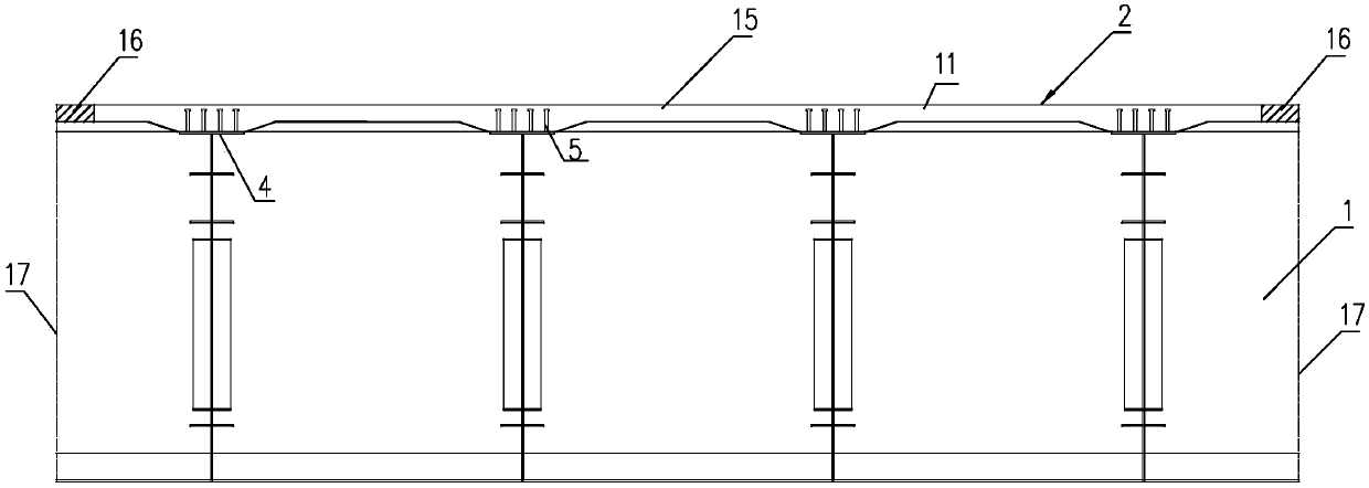
[0009] The purpose of the present invention is to provide an ultra-high performance concrete (UHPC) bridge deck with high tensile and compressive strength, reliable connection, good durability and low cost, which can effectively solve the problem of using orthotropic steel bridge decks Fatigue cracking caused by fatigue cracking, bridge deck pavement damage and ordinary concrete bridge deck are easy to crack and other problems that have plagued the engineering field for a long time. It is suitable for PK steel box composite beams, closed steel box composite beams, edge steel box composite beams, and I-beam composite beams. and steel truss composite beams, etc.
[0011] The present invention significantly improves the local stiffness of the bridge deck, and solves the problem of fatigue cracking that has plagued the engineering field for a long time caused by the use of orthotropic steel decks; moreover, the bonding performance and mutual coordination deformation performance of UHPC and asphalt concrete are better, It avoids the risk of easy failure of the bond between the orthotropic steel bridge deck and the asphalt wear layer and the risk of easy damage to the asphalt pavement layer, and the bridge deck can be paved with conventional asphalt concrete

Method used


Image

  • Ultrahigh-performance concrete bridge deck
  • Ultrahigh-performance concrete bridge deck
  • Ultrahigh-performance concrete bridge deck

Examples


Embodiment 1

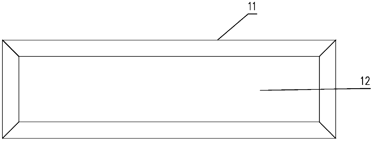
[0040] Such as Figure 1-7 Shown is an ultra-high-performance concrete bridge deck 2 of the present invention, which is formed by connecting ultra-high-performance concrete slabs 11 arranged in an array. The bottom surface of the ultra-high-performance concrete slab 11 is groove-shaped. Groove 12 is the flat quadrangular truncated pyramid shape that is gradually included from top to bottom, see Figure 7 , the ultra-high performance concrete slab 11 is provided with a steel mesh connected by steel bars arranged along the two main directions of stress. In this embodiment, two upper and lower layers of steel mesh are arranged according to the distribution of positive and negative bending moments. The main reinforcement adopts C16-C25 steel bars 7, and the distribution bars in the other direction use C12-C20 steel bars 71. The connecting section between two adjacent ultra-high performance concrete slabs 11 is the connecting section of ultra-high performance concrete slabs. The c...

Embodiment 2

[0051] Such as Figure 8 and 9 As shown, the difference between this embodiment and Embodiment 1 is that the wet joint is located at the mid-span position, each prefabricated section 15 is formed by connecting several complete ultra-high performance concrete slabs 11, and two adjacent prefabricated sections 15 A part of the ultra-high-performance concrete slab 11 is connected through a cast-in-place section 16 to form a complete ultra-high-performance concrete slab 11. The cast-in-place section 16 uses a steel plate 9 with a shear stud 5 as a formwork for wet joints and then casts an ultra-high-performance concrete slab. After the concrete is formed, therefore, local UHPC composite bridge decks with shear nails can also be used for the cast-in-place sections within the range of about 500mm on both sides of the construction joint. When the wet joints use UHPC composite bridge decks with steel plates with shear nails at the bottom , its steel plate can also be used as a templat...

Embodiment 3

[0053] Such as Figure 10 and 11 As shown, the difference between this embodiment and Embodiment 1 is that the wet joints are located at the upper flanges 4 of the beams and longitudinal beams 3, and each prefabricated section 15 is connected by several complete ultra-high performance concrete slabs 11. The cast-in-place section 16 is an ultra-high performance concrete slab connection section connected with the main beam 1.


PUM


Abstract

The invention discloses an ultrahigh-performance concrete bridge deck. The ultrahigh-performance concrete bridge deck is formed in the manner that ultrahigh-performance concrete slabs arranged in an array are connected into a whole. The bottom face of each ultrahigh-performance concrete slab is in a groove shape. Each groove is in a flat quadrangular pyramid frustum shape which becomes wider gradually from top to bottom. Reinforcing meshes formed in the manner that steel reinforcing bars arranged in the two stress main directions are connected into a whole are arranged in the ultrahigh-performance concrete slabs. The connection section between every two adjacent ultrahigh-performance concrete slabs is an ultrahigh-performance concrete slab connection section. All or a part of the ultrahigh-performance concrete slab connection sections are connected with inner components of a main beam below the bridge deck. By the adoption of the ultrahigh-performance concrete bridge deck, the local rigidity of the bridge deck is improved, and the fatigue cracking problem caused by an orthotropic steel bridge deck is solved; the adhesive performance and mutual coordination deformation between UHPCand bituminous concrete are good, the risks that adhesion between the orthotropic steel bridge deck and a pitch wearing layer is prone to ineffectiveness and a pitching pavement layer is prone to damage are solved, and bridge deck pavement can adopt conventional bituminous concrete.

Description

technical field [0001] The present invention relates to an ultra high performance concrete (UHPC) bridge deck. Background technique [0002] The orthotropic steel bridge deck is composed of a steel roof, longitudinal stiffeners and diaphragms connected by welds. It has a series of advantages such as light weight, large ultimate bearing capacity, and short construction period, and is widely used in large-span bridges. In bridges, due to factors such as low stiffness of steel bridge decks, poor bonding performance with asphalt concrete, and poor mutual coordination and deformation performance, many orthotropic steel bridge decks in service have fatigue cracking and pavement damage ( ruts, potholes) and many other diseases; and the use of heavier ordinary concrete decks to replace the orthotropic steel decks on the steel girders, although the fatigue of the orthotropic steel decks has been solved, but due to its own lower tensile strength Low, not only the slab is thicker, the...

Claims


Application Information

Patent Timeline
Patent Type & Authority Applications(China)
IPC IPC(8): E01D19/12
Inventor 梁立农王诚郭文华黄湛军李旭华刘安兴黎敏王强
Owner GUANGDONG PROVINCE COMM PLANNING & DESIGN INST
Learn More