Abrasive particle monitoring sensor of oil

A technology for monitoring sensors and oil abrasive particles, which is used in measuring devices, particle size analysis, scientific instruments, etc., can solve problems such as poor monitoring results, and achieve reduced sensor size, strong anti-interference ability, non-contact measurement and low cost. Effect

Pending Publication Date: 2018-01-16
GUILIN UNIV OF ELECTRONIC TECH
View PDF0 Cites 10 Cited by
  • Summary
  • Abstract
  • Description
  • Claims
  • Application Information

AI Technical Summary

Problems solved by technology

[0004] What the present invention aims to solve is the problem that the monitoring effect of the existing oil abrasive particle monitoring method is not good, and an oil abrasive particle monitoring sensor is provided

Method used


Image

  • Abrasive particle monitoring sensor of oil
  • Abrasive particle monitoring sensor of oil
  • Abrasive particle monitoring sensor of oil

Examples


Embodiment Construction

[0020] In order to make the object, technical solution and advantages of the present invention clearer, the present invention will be further described in detail below in combination with specific examples and with reference to the accompanying drawings.

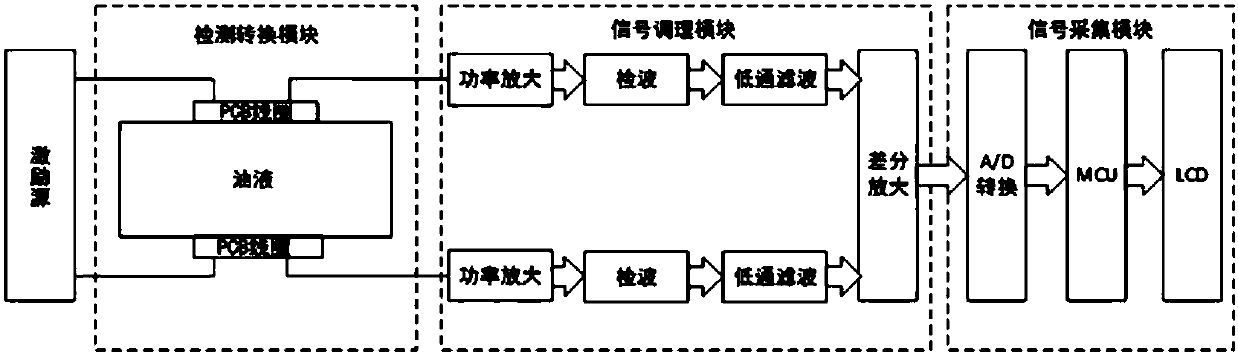
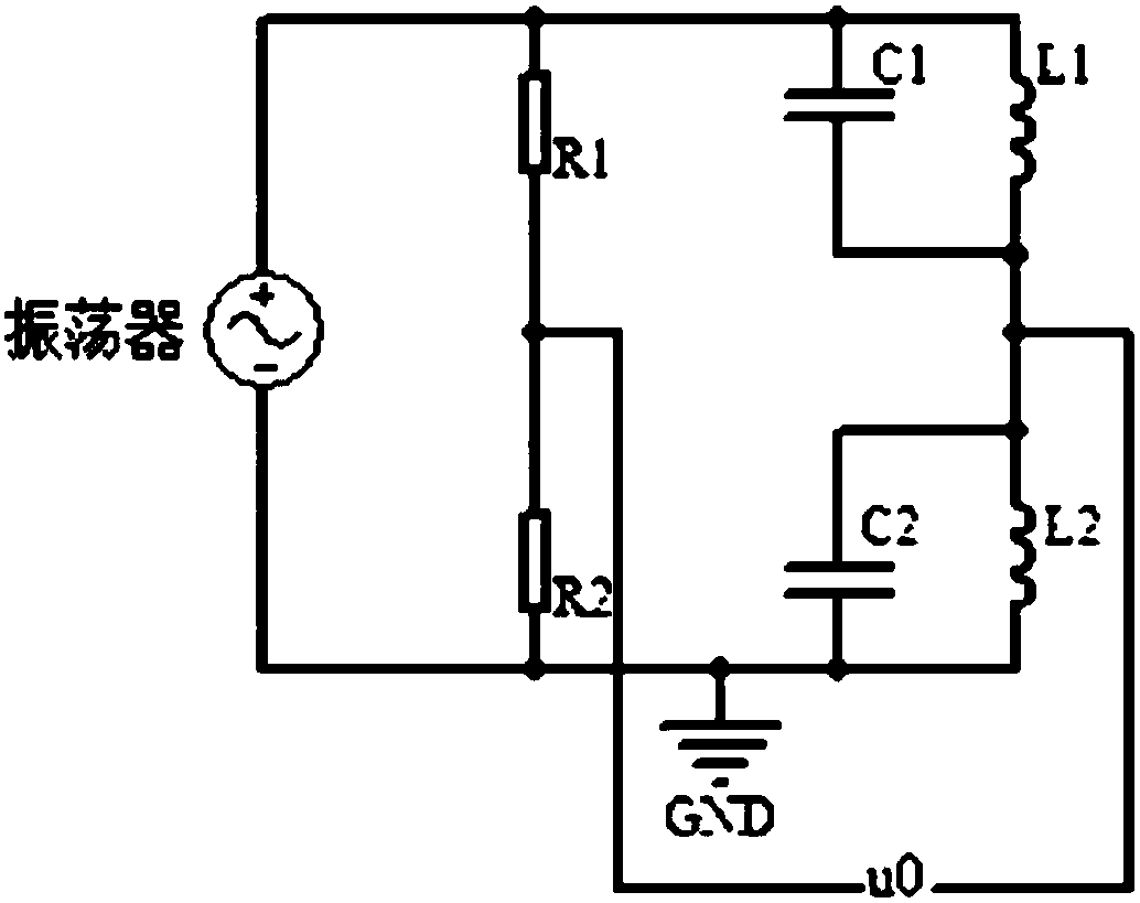
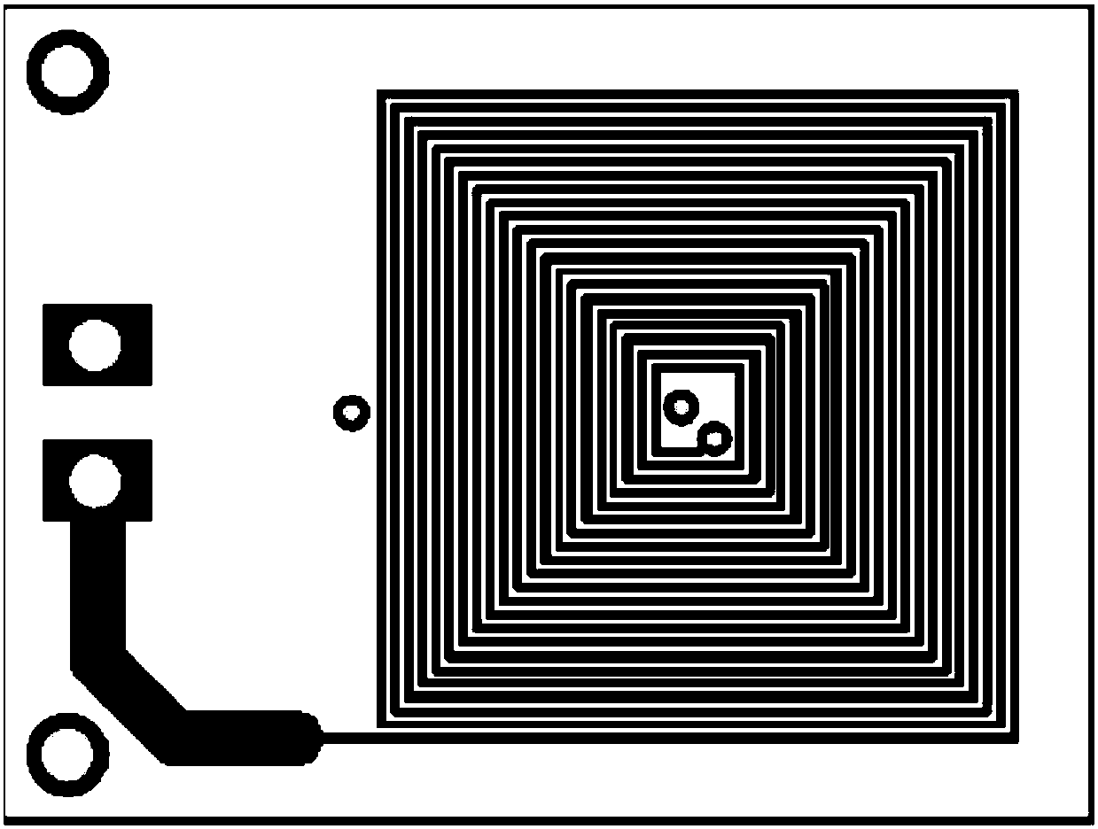
[0021] An oil wear particle monitoring sensor such as figure 1 As shown, it is mainly composed of excitation source, detection conversion module, signal conditioning module and signal acquisition module.

[0022] The above-mentioned excitation source is a sinusoidal signal generator with controllable frequency. The sensitivity of the sensor can be adjusted by controlling the frequency of the excitation source. The excitation frequency can be selected according to the diameter of the oil pipe. High-frequency excitation can obtain better sensitivity when the pipe diameter is small. When the liquid pipe diameter is large, low-frequency excitation can be used to obtain better sensitivity, and the specific parameters are adjusted...


PUM


Abstract

The invention discloses an abrasive particle monitoring sensor of oil. The sensor mainly comprises an excitation source, a detection conversion module, a signal conditioning module and a signal acquisition module, wherein the detection conversion module comprises two identical PCB (printed circuit board) planar coils, two identical capacitors and two identical resistors. The signal conditioning module comprises two identical conditioning branches and a differential amplification circuit; input ends of the two conditioning branches form two input ends of the signal conditioning module and are connected with an output end of the detection conversion module; output ends of the two conditioning branches are connected with two input ends of the differential amplification circuit; and an outputend of the differential amplification circuit forms an output end of the signal conditioning module and is connected with an input end of the signal acquisition module. The current vortex based PCB planar coil sensor has the characteristics of simple structure, high sensitivity, a wide linear range, high interference resistance, non-contact measurement, low cost and the like.

Description

technical field [0001] The invention relates to the technical field of oil monitoring, in particular to an oil abrasive particle monitoring sensor. Background technique [0002] High-speed machinery is prone to produce metal abrasive particles due to wear and tear. These abrasive particles will pollute the mechanical lubrication system and cause machine failure. At the same time, a statistical data on the fault diagnosis of mechanical equipment shows that 80% of the failure of mechanical equipment is caused by the failure of the lubrication system caused by abnormal wear. Therefore, for the industry, effective oil wear monitoring plays an important role in environmental safety, preventing mechanical equipment failure and predicting the life of mechanical equipment. [0003] At present, there are optical detection methods, capacitance detection methods and acoustic detection methods for monitoring oil wear particles. The accuracy of the optical detection method is easily af...

Claims


Application Information

Patent Timeline
Patent Type & Authority Applications(China)
IPC IPC(8): G01N15/02G01N15/06
Inventor 张应红文立超黄祥官韦祥礼陈国信王标黄智聪李彩林傅旭东贾霈泓薛世睿
Owner GUILIN UNIV OF ELECTRONIC TECH
Why Eureka
Try Eureka