Electric driving device

一种电动驱动、电动机的技术,应用在机电装置、电动组件、冷却/通风装置等方向,能够解决磁传感器磁检测误差等问题,达到减小检测误差、抑制性能的下降、提高自由度的效果

Active Publication Date: 2018-01-16
MITSUBISHI ELECTRIC CORP
View PDF7 Cites 8 Cited by
  • Summary
  • Abstract
  • Description
  • Claims
  • Application Information

AI Technical Summary

Problems solved by technology

In the above-mentioned conventional motor, for example, if a wire through which current flows is arranged around the magnetic sensor, the noise magnetic field generated by the wire acts on the magnetic sensor, thereby easily generating a magnetic detection error of the magnetic sensor.

Method used


Image

  • Electric driving device
  • Electric driving device
  • Electric driving device

Examples


Embodiment approach 1

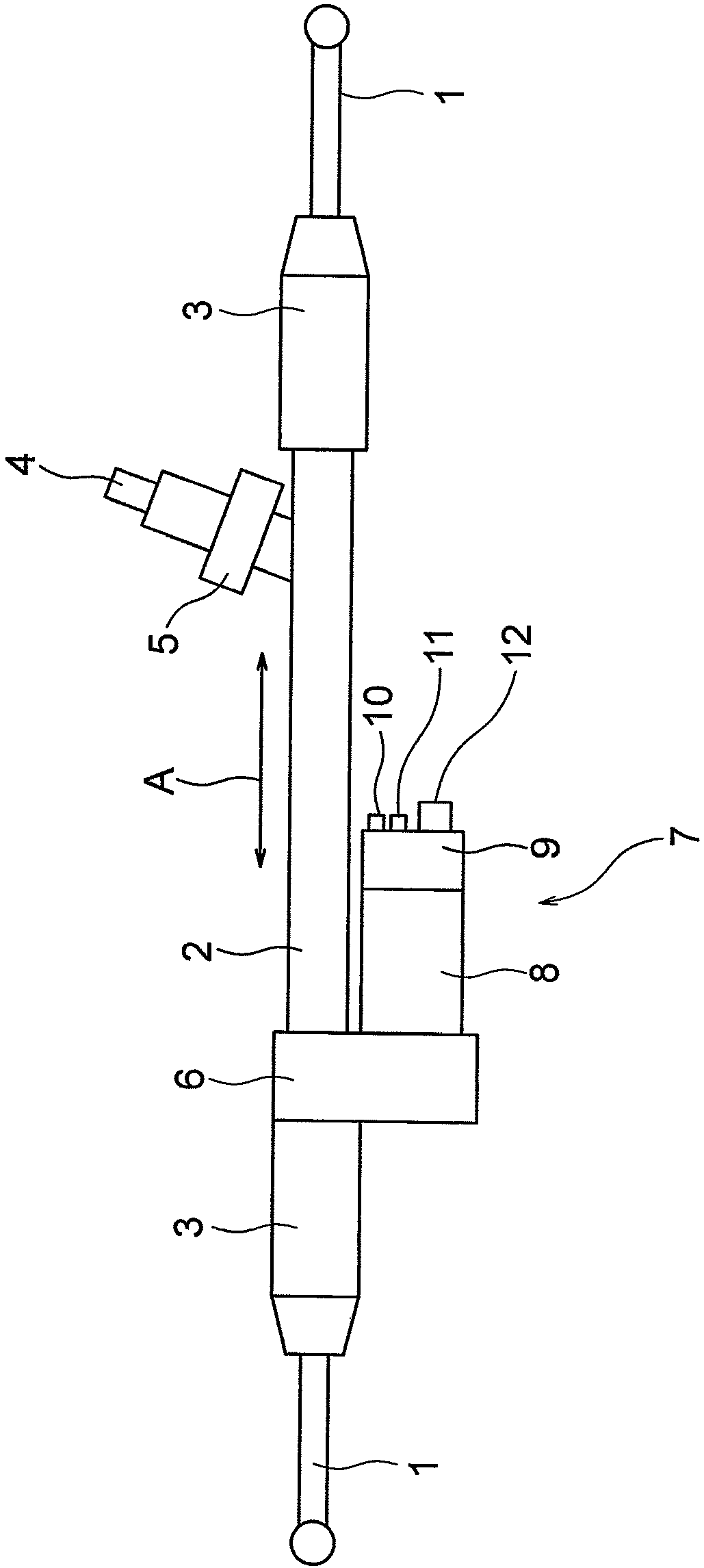
[0034] figure 1 It is a configuration diagram showing the electric power steering device according to Embodiment 1 of the present invention. The electric power steering device according to the present embodiment is, for example, a vehicle electric power steering device mounted on a vehicle such as an automobile. A rack shaft (not shown) accommodated in the case 2 is connected between the pair of link rods 1 . The joints between the respective connecting rods 1 and the rack shafts are accommodated in rack boots 3 that prevent foreign matter from entering the electric power steering apparatus. The rack shaft is connected to shaft 4. When the driver turns the steering wheel (not shown), the torque generated by the steering is transmitted to the rack shaft via the steering shaft (not shown) and the shaft 4 . The shaft 4 is provided with a torque sensor 5 that detects a torque generated by turning the steering wheel. Furthermore, an electric drive 7 is arranged on the rack shaf...

Embodiment approach 2

[0092] In Embodiment 1, the current phase difference of each power supply line 26 is 0° between the U1 phase and the U2 phase, between the V1 phase and the V2 phase, and between the W1 phase and the W2 phase. However, it may also be between the U1 phase and the U2 phase Between phases, between V1 phase and V2 phase, and between W1 phase and W2 phase, the current phase difference of each power supply line 26 is set to 30°. That is, in the present embodiment, the current phases of the power supply lines 26 differ by 30° between the U1 phase and the U2 phase, between the V1 phase and the V2 phase, and between the W1 phase and the W2 phase. Other structures are the same as those in Embodiment 1.

[0093] Next, in this embodiment, the positional relationship between each power supply line 26 and the rotation sensor 44 is Figure 7 The influence of the magnetic field from each power supply line 26 on the rotation sensor 44 at the time of the positional relationship will be describe...

Embodiment approach 3

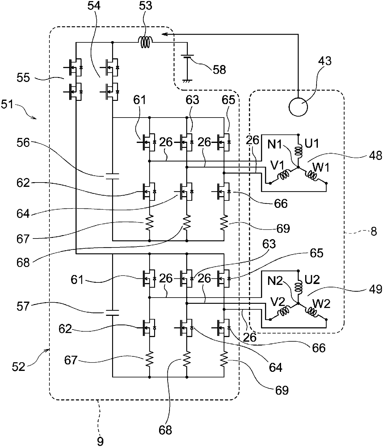
[0101] In Embodiment 1, electric current flows through each feeding line 26 , but only a part of the current flowing through each feeding line 26 may always be stopped. In this embodiment, among the currents flowing through the power supply lines 26 of the U1 phase, V1 phase, W1 phase, U2 phase, V2 phase, and W2 phase, the current flows through the power supply lines 26 of the U1 phase, V1 phase, and W1 phase, And only the current flowing through the power supply lines 26 of the U2 phase, the V2 phase, and the W2 phase is always stopped. That is, in the present embodiment, in the first and second three-phase AC coils 48 and 49, only the inverter circuit 38 supplies three-phase power to the first three-phase AC coil 48, and the slave inverter circuit 38 The power supply to the second three-phase AC winding 49 is always stopped. Other structures are the same as those in Embodiment 1.

[0102] Next, in this embodiment, the positional relationship between each power supply line ...


PUM


Abstract

An electric driving device, in which a sensor magnet is fixed to a first end section of the rotation shaft of a motor. A sensor device has a rotation sensor for detecting the magnetic field of the sensor magnet. The rotation sensor faces the sensor magnet along the axial direction of the rotation shaft. A control unit mounted on the motor has an inverter circuit connected to the armature coil of the motor via a plurality of power supply wires. The inverter circuit is disposed, with respect to the axial direction of the rotation shaft, at a position further from the sensor magnet than the rotation sensor. A shield plate comprising a magnetic material is disposed between the rotation sensor and the inverter circuit.

Description

technical field [0001] The invention relates to an electric drive with a control unit mounted on an electric motor. Background technique [0002] Conventionally, there is known a motor in which a magnet is attached to the end of the shaft of the rotor, a magnetic sensor is made to face the magnet on the axis of the shaft, and the magnetic sensor measures the magnetism of the magnet to detect the rotation angle of the rotor. The current supplied to the stator windings is controlled. In the conventional motor described above, for example, if a lead wire through which current flows is arranged around the magnetic sensor, a noise magnetic field generated by the lead wire acts on the magnetic sensor, and a magnetic detection error of the magnetic sensor tends to occur. [0003] Conventionally, in order to suppress the occurrence of detection errors in the magnetic sensor, a motor has been proposed in which first and second wires through which currents of the same phase flow are ...

Claims


Application Information

Patent Timeline
Patent Type & Authority Applications(China)
IPC IPC(8): H02K11/20H02K11/30H02K5/00
CPCH02K5/00H02K11/00H02K29/08H02K9/227H02K11/215H02K11/23H02K11/33B62D5/0406H02K5/15
Inventor 泷泽勇二阿久津悟市川崇敬伏江俊祐
Owner MITSUBISHI ELECTRIC CORP
Why Eureka
Try Eureka