Technological cover plate of combined structure and preparation method

A combined structure and cover plate technology, which is applied in the field of composite material manufacturing, can solve the problems of skin body position mismatch, position mismatch, and high quality requirements on the outer surface, so as to improve the coordination of internal structure activities and reduce the occurrence of flashing Possibility, improve the effect of separation and lapping effect

Active Publication Date: 2018-01-19
CHENGDU AIRCRAFT INDUSTRY GROUP
View PDF1 Cites 6 Cited by
  • Summary
  • Abstract
  • Description
  • Claims
  • Application Information

AI Technical Summary

Problems solved by technology

[0003] However, the high rigidity performance of the composite material process cover plate leads to poor coordination of activities and easily causes position mismatch, especially the high quality requirements of the outer surface, and the special-shaped skin formed by male mold
The special-shaped skin is rich in R-zones, knuckles, and breakpoints, and it is extremely difficult to prepare. If the traditional composite material technology cover plate is used, although the high-quality surface of the special-shaped skin is given, due to its high rigidity, the coordination of internal structure activities is poor. It is easy to cause position mismatch with the skin body, resulting in structural mutation areas such as R areas, knuckles, and breakpoints, forming internal defects such as knuckle protrusions, resin-rich, and delaminated, which obviously cannot meet the requirements for the manufacture of such composite special-shaped skins. need

Method used


Image

  • Technological cover plate of combined structure and preparation method
  • Technological cover plate of combined structure and preparation method
  • Technological cover plate of combined structure and preparation method

Examples


Embodiment 1

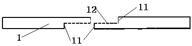
[0035] The present invention is realized through the following technical solutions, as figure 1 As shown, a combined structure process cover plate is used for the manufacture of composite material structures, including a plurality of overlapping split-body shaped panels 1, and the split-body shaped panels 1 include a boundary portion provided with a stepped surface and a The connection part where the boundary part is far away from the end of the stepped surface is connected, and the boundary part and the connection part are solidified and formed at one time. The split shaped panels 1 overlap each other through stepped surfaces.

[0036] It should be noted that, through the above improvements, the stepped surfaces completely contact each other and overlap each other. The coordination of the internal structure of the process cover is improved, the degree of bonding between the process cover and the skin body is optimized, and the internal quality is guaranteed to the greatest e...

Embodiment 2

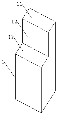
[0039] This embodiment is further optimized on the basis of the above embodiments, such as figure 1 As shown, the stepped surface includes a middle boundary surface 12 and two edge boundary surfaces 11, the middle boundary surface 12 is parallel to the upper plane / lower plane of the connecting part of the split forming surface, and the two edge boundary surfaces 11 It is perpendicular to the upper plane / lower plane of the connection part of the split panel 1 . Taking the surface perpendicular to the edge boundary surface and the middle boundary surface as the reference surface, the projection on the reference surface of the middle boundary surface 12 is the middle boundary contour line, and the length of the middle boundary contour line is between 0 mm and 10 mm; The projection of the edge boundary surface 11 on the reference surface is an edge contour line, the projection of the connection surface on the reference surface is a connection contour line, and the length of the ed...

Embodiment 3

[0045] This embodiment is further optimized on the basis of the above embodiments, such as figure 1 As shown, the split shaped panel 1 is made of composite material, the reinforcement includes one or more of carbon fiber, glass fiber, and aramid fiber, and the form of the reinforcement is unidirectional, plain weave, or twill weave , one or more of satin; the resin matrix includes epoxy resin, bismaleimide resin, polyimide resin, polybenzoxazine resin, cyanate resin, phenolic resin, not One or more of saturated resins.

[0046] The reinforcing body is any one of a material composed of carbon fiber material and glass fiber material, a material composed of carbon fiber material and aramid fiber material, a material composed of carbon fiber material, glass fiber material and aramid fiber material.

[0047] Other parts of this embodiment are the same as those of the foregoing embodiments, so details are not repeated here.


PUM

PropertyMeasurementUnit
lengthaaaaaaaaaa
lengthaaaaaaaaaa
lengthaaaaaaaaaa

Abstract

The invention discloses a technological cover plate of a combined structure. The technological cover plate comprises a plurality of split shaped panels in lap joint, and the split shaped panels comprise border parts provided with step surfaces and connecting parts connected with the ends, away from the step surfaces, of the border parts; the border parts and the connecting parts are molded throughone-time curing; and the split shaped panels are in lap joint through the step surfaces. According to the technological cover plate, the border parts with the step surfaces are adopted, motion coordination of internal structures of the technological cover plate is improved, the fitting degree of the technological cover plate and skin green bodies is optimized, and internal quality is guaranteed;lap joint clearances are prevented from being generated, the possibility of the material overflow problem is reduced, even though the material overflow problem occurs, only resin overflows, and overflowed materials can be treated through simple polishing; and the operation program is effectively simplified, the separated lap joint effect of the split shaped panels is improved, the possibility of material overflow at lap joint zones of the split panels is reduced, the structure is unique, the concept is novel, and the prepared technological cover plate of the combined structure has high structure motion coordination of rubber technological cover plates.

Description

technical field [0001] The invention relates to the technical field of composite material manufacturing, in particular to a composite structure process cover plate and a preparation method thereof. Background technique [0002] The process cover is a commonly used auxiliary forming tool for manufacturing composite skin structures. Among them, the process cover of composite material is based on its own stiffness and high-quality forming surface, and is currently widely used in the field of aerospace and other high-end composite structure manufacturing. application. [0003] However, the high rigidity performance of the composite material process cover plate leads to poor coordination of activities and easily causes position mismatch, especially the high-quality external surface, which uses a male mold to form a special-shaped skin. The special-shaped skin is rich in R-zones, knuckles, and breakpoints, and it is extremely difficult to prepare. If the traditional composite mat...

Claims


Application Information

Patent Timeline
Patent Type & Authority Applications(China)
IPC IPC(8): B29C70/54
Inventor 文友谊祝君军李博文琼华唐建明刘立朋叶宏军
Owner CHENGDU AIRCRAFT INDUSTRY GROUP
Why Eureka
Try Eureka