SPE membrane electrode and preparation technology thereof

A preparation process, membrane electrode technology, applied in the direction of electrodes, electrode shape/type, electrolysis process, etc., can solve the problems of low production efficiency, long spraying time, long spraying working hours, etc., to reduce the number of preparations and simplify the spraying process effect of shortening preparation time

Pending Publication Date: 2018-01-19
浙江高成绿能科技有限公司
View PDF0 Cites 6 Cited by
  • Summary
  • Abstract
  • Description
  • Claims
  • Application Information

AI Technical Summary

Problems solved by technology

[0004] 1. When the proton exchange membrane is made into a membrane-forming electrode assembly, only the middle part becomes an effective catalytic area, so the utilization rate of the proton exchange membrane is low and the dosage is large;
[0005] 2. In order to ensure the area of ​​the blank area, the catalyst needs to be carefully sprayed during the spraying process, especially at the junction of the blank area and the effective catalytic area, the spraying time is long, the fault tolerance rate is low, and the production efficiency is low;
[0006] 3. Because the catalyst is prepared as a suspension, and the amount of a single proton exchange membrane is not large, and the spraying time is too long due to the disadvantage 2, if too much catalyst is prepared, the unused part is prone to sedimentation, so it is not suitable for Large-capacity catalyst preparation can only be prepared one by one, which is time-consuming and laborious;
[0007] 4. Membrane electrodes have low production efficiency and low output, which seriously restricts the overall output efficiency of SPE electrolytic cells and has become a major pain point and bottleneck in the production of SPE electrolytic cells.

Method used


Image

  • SPE membrane electrode and preparation technology thereof
  • SPE membrane electrode and preparation technology thereof
  • SPE membrane electrode and preparation technology thereof

Examples


Embodiment 1

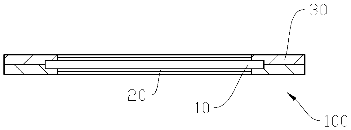
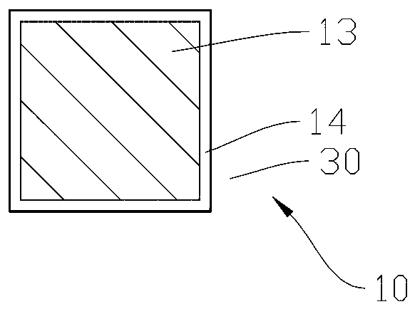
[0052] Embodiment 1: as Figure 1-3 As shown, a kind of SPE membrane electrode is installed in the SPE electrolytic cell that comprises membrane electrode 100, bipolar plate 200, end plate 300, gasket 400, and membrane electrode 100 comprises proton exchange membrane 10, and the catalyst embedded in proton exchange membrane 10 20 , a polyester frame 30 surrounding the outer edge and responsible for connecting with the bipolar plate 200 .

[0053] The proton exchange membrane 10 includes a feeding area 13 for embedding the catalyst 20 , and an unloading area 14 located on the edge of the feeding area 13 for connecting with a polyester frame 30 .

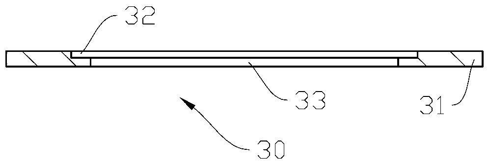
[0054] The polyester frame 30 includes a polyester frame substrate 31 whose edge is adapted to the shape and size of the bipolar plate 200, an inner frame 32 for placing the proton exchange membrane 10 in the middle of the polyester frame substrate 31, and an inner frame 32 The through cavity 33 in the middle is used to expose the ca...

Embodiment 2

[0061] Embodiment 2: as figure 1 , 4 Shown, a kind of SPE membrane electrode preparation process comprises the following steps:

[0062] A) Catalyst spraying preparation: After removing the organic and inorganic impurities on the proton exchange membrane 10, fix the entire proton exchange membrane on the spraying station, and separate the entire proton exchange membrane into integer A proton exchange membrane with a catalytically active area in a single proton exchange membrane;

[0063] B) Catalyst spraying: prepare the catalyst 20, use the spraying equipment to spray the catalyst 20 evenly on the whole proton exchange membrane, and let it dry after spraying;

[0064] C) Proton exchange membrane cutting: tear off the tape used in step A, and cut the entire proton exchange membrane treated in step B into multiple single proton exchange membranes based on the unsprayed area;

[0065] D) Hot pressing preparation: use high-temperature adhesive tape to center the single proton...

Embodiment 3

[0071] Embodiment 3: as figure 1 , 4 Shown, a kind of SPE membrane electrode preparation process comprises the following steps:

[0072] A) Catalyst spraying preparation: After removing the organic and inorganic impurities on the proton exchange membrane 10, fix the entire proton exchange membrane on the spraying station, and separate the entire proton exchange membrane into integer A proton exchange membrane with a catalytically active area in a single proton exchange membrane;

[0073] B) Catalyst spraying: prepare the catalyst 20, use the spraying equipment to spray the catalyst 20 evenly on the whole proton exchange membrane, and let it dry after spraying;

[0074] C) Proton exchange membrane cutting: tear off the tape used in step A, and cut the entire proton exchange membrane treated in step B into multiple single proton exchange membranes based on the unsprayed area;

[0075] D) Hot pressing preparation: use high-temperature adhesive tape to center the single proton...


PUM


Abstract

The invention discloses an SPE membrane electrode which is arranged in an SPE electrolytic cell comprising the SPE membrane electrode, a bipolar plate, an end plate and a sealing gasket. The SPE membrane electrode comprises a proton exchange membrane, a catalyst embedded into the proton exchange membrane, and a polyester frame surrounding the edge of the surface of the bipolar plate and being in charge of connecting with the bipolar plate. The invention further discloses a preparation technology of the SPE membrane electrode. The preparation technology comprises the steps of catalyst sprayingpreparation, catalyst spraying, proton exchange membrane clipping, hot pressing preparation, hot pressing and post treatment. The SPE membrane electrode is simple in structure, convenient to manufacture and low in cost; the utilization ratio of the proton exchange membrane is raised significantly; the consumption of the proton exchange membrane is reduced; the cost of the SPE membrane electrode islowered; the connecting strength between the membrane electrode and the bipolar plate is ensured and improved; the spraying efficiency of the catalyst and the manufacturing efficiency of the SPE membrane electrode are improved substantially; and the productive capacity potential of the SPE electrolytic cell is released fully.

Description

technical field [0001] The invention relates to the field of hydrogen production by SPE electrolysis of water, in particular to an SPE membrane electrode and a preparation process thereof. Background technique [0002] Hydrogen energy is the most ideal energy source in the future. Hydrogen production by electrolysis of water has broad development prospects. SPE electrolysis of water for hydrogen production, that is, Solid Polymer Electrolyte electrolysis of water for hydrogen production, is called solid polymer electrolyte electrolysis of water for hydrogen production technology. The core of this technology is a solid polymer electrolyte electrolysis cell, such as attached Figure 5 As shown, the SPE electrolytic cell is generally composed of a membrane electrode 100, a bipolar plate 200, an end plate 300, and a gasket 400. The left and right sides of the membrane electrode 100 are provided with a bipolar plate 200, and the membrane electrode 100 and the bipolar plate 200 a...

Claims


Application Information

Patent Timeline
Patent Type & Authority Applications(China)
IPC IPC(8): C25B11/02C25B11/04C25B1/04
CPCY02E60/36
Inventor 范峰强李叶涛侯向理姚宇希
Owner 浙江高成绿能科技有限公司
Why Eureka
Try Eureka