
Method for detecting dissimilar material pipeline sectional area loss based on ultrasonic guided-wave technology

A technology of ultrasonic guided wave and detection method, which is applied in the direction of material analysis, measuring device, and analysis material using sound wave/ultrasonic wave/infrasonic wave, which can solve the problems such as difficulty in ensuring detection accuracy and reliability, reducing detection efficiency, and loss of magnetic energy. Achieve the effect of improving the range and detection efficiency

Inactive Publication Date: 2018-01-19
ANHUI SCI & TECH UNIV
View PDF2 Cites 2 Cited by
  • Summary
  • Abstract
  • Description
  • Claims
  • Application Information

AI Technical Summary

Problems solved by technology

In the magnetic flux detection method, due to the external magnetic source, there is leakage flux, resulting in loss of magnetic energy, thereby reducing the detection efficiency; in the magnetic bridge circuit method, the debugging and testing of the detection method are more complicated due to the integration of multiple magnetic circuits.
These two methods are relatively complicated to detect the cross-sectional area loss of pipelines made of different materials, and it is difficult to guarantee the accuracy and reliability of the detection.

Method used


Image

  • Method for detecting dissimilar material pipeline sectional area loss based on ultrasonic guided-wave technology
  • Method for detecting dissimilar material pipeline sectional area loss based on ultrasonic guided-wave technology
  • Method for detecting dissimilar material pipeline sectional area loss based on ultrasonic guided-wave technology

Examples


Embodiment 1

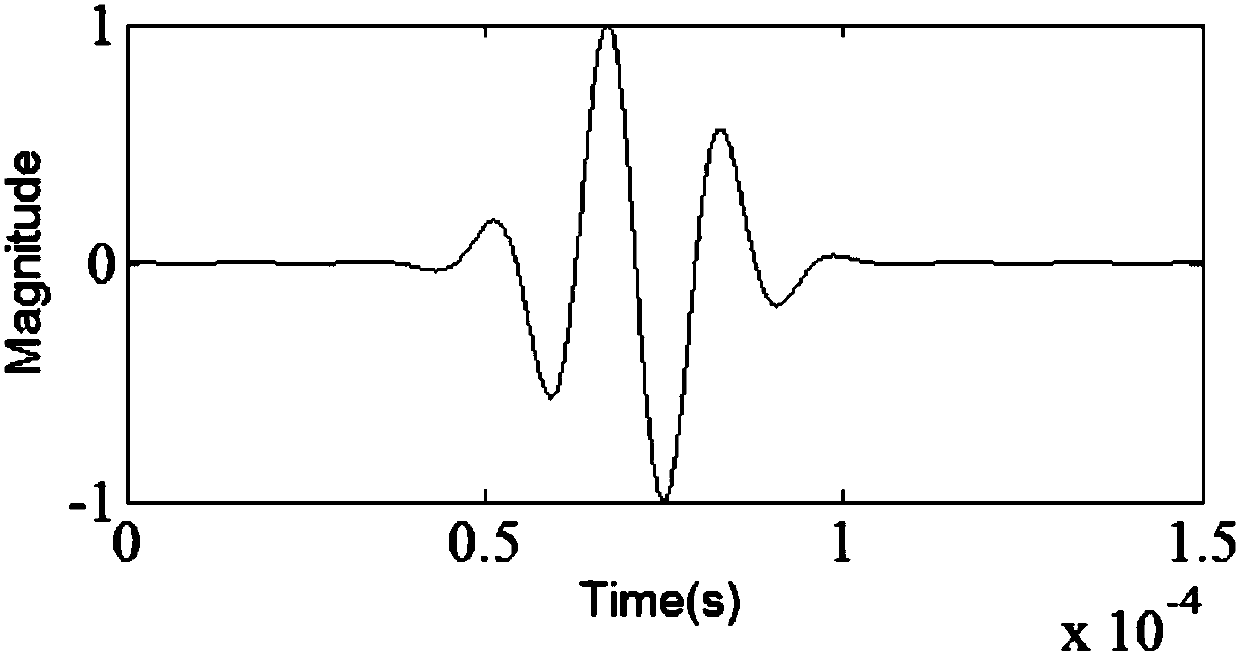
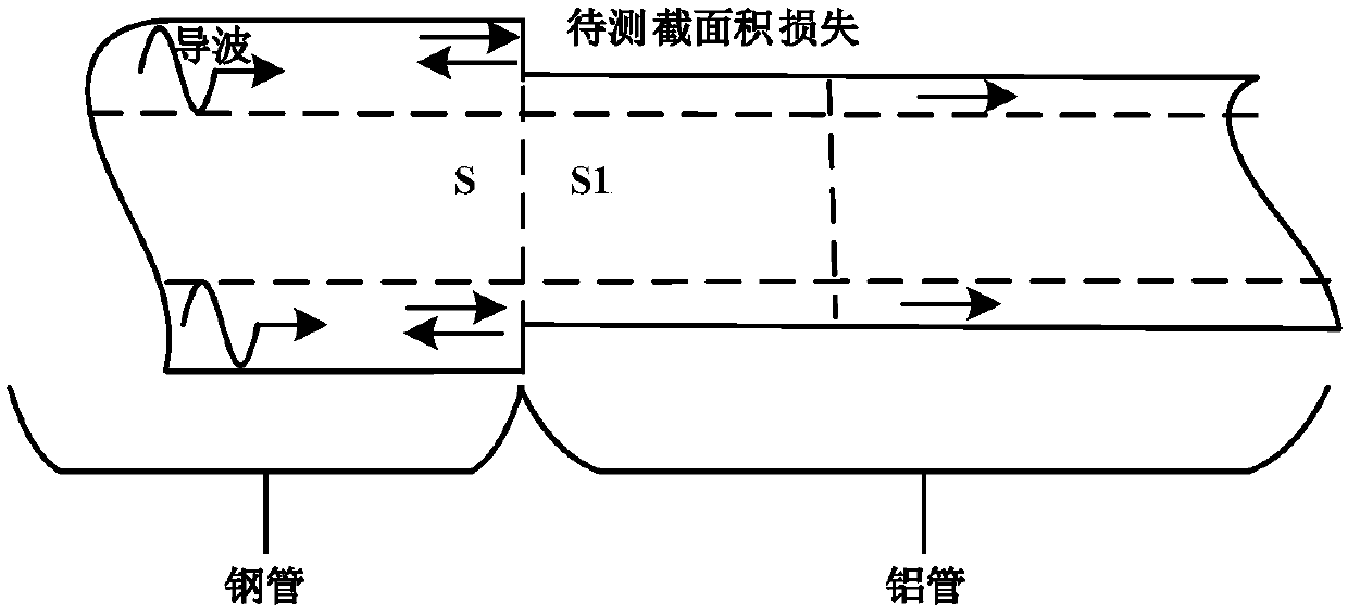
[0026] Such as figure 2 , 3 The principle diagram of pipeline detection of dissimilar materials and the schematic diagram of cross-sectional area loss are shown. In this embodiment, the specific two-material pipeline is taken as an example to expand the guided wave detection of cross-sectional area loss in the pipeline. The implementation process is as follows:

[0027] 1) Here, the cross-sectional area loss detection of guided wave technology is realized by simulating dissimilar material pipes. Using the three-dimensional simulation software ABAQUS, according to the parameters in Table 1 and Table 2, the physical model of the pipeline with different materials is established.

[0028] Table 1 pipeline parameters

[0029]

[0030] Table 1 shows the pipe parameters for steel pipes and Table 2 shows the parameters for aluminum pipes.

[0031] Table 2 pipeline parameters

[0032]

[0033] Steps such as setting components and material properties in ABAQUS, the two materi...


PUM


Abstract

The invention discloses a method for detecting dissimilar material pipeline sectional area loss based on an ultrasonic guided-wave technology, which belongs to the field of nondestructive test of a pipeline. The method is characterized in that an incident signal form is selected, measurement is carried out to obtain a cross-sectional area of the to-be-measured pipeline, and the result is recordedas S0, the cross-sectional area of the dissimilar material pipeline sectional area loss position which is required for being detected in the pipeline is recorded as S1, the density of the pipeline andthe dissimilar material at the to-be-measured sectional area loss position can be recorded as Rho0 and Rho1; the young modulus and Poisson's ratio of the pipeline and the dissimilar material at the sectional area loss position are recorded as E0, v0 and E1 and v1; the guided wave propagation speed of the pipeline and the dissimilar material at the sectional area loss position is obtained and according to the formula shown as the specification, a guided-wave detection device is employed for detecting the to-be-measured pipeline by using appropriate detection frequency, a guided-wave detectionsignal is obtained, an amplitude value Ar and an amplitude value Ai of a reflection signal and the guided-wave incident signal at the sectional area loss position can be obtained, calculation is carried out according to an equation of T=Ar / Ai, and the cross-sectional area of the dissimilar material at the sectional area loss position is obtained according to the formula shown as the specification.The detection method has important engineering value.

Description

technical field [0001] The invention relates to a detection method for cross-sectional area loss of pipelines of different materials based on ultrasonic guided wave technology, and belongs to the field of non-destructive detection of pipelines. Background technique [0002] As an important transmission strategy, pipelines have been widely used in industrial production and living fields such as petroleum, chemical, natural gas, and thermal pipelines, and their safety performance is very important. Metal sectional area loss is a relatively common and very important pipeline defect. Fast, reliable and effective pipeline sectional area loss detection technology has always been a difficult problem in nondestructive testing, especially for pipelines composed of different materials. The detection of area loss will be more complicated and difficult. [0003] Ultrasonic guided wave testing technology is widely used in non-destructive testing (NDT, Non-Destructive Testing) ) and Str...

Claims


Application Information

Patent Timeline
IPC IPC(8): G01N29/44G01N29/024
Inventor 柳伟续张新伟
Owner ANHUI SCI & TECH UNIV
Learn More