Electron beam irradiation device

一种电子射线、照射装置的技术,应用在电子射线照射装置领域

Active Publication Date: 2018-01-19
AIREX
View PDF4 Cites 6 Cited by
  • Summary
  • Abstract
  • Description
  • Claims
  • Application Information

AI Technical Summary

Problems solved by technology

[0006] In the method based on hydrogen peroxide gas, although a required level of sterilization effect can be obtained, a certain degree of processing time is required to sterilize the entire package, and when hydrogen peroxide gas is passed through Tyvek ( Tyvek) (trademark) when the top surface seal member enters the inside of the plastic barrel, there is a problem that it takes time to remove the hydrogen peroxide condensed inside

Method used


Image

  • Electron beam irradiation device
  • Electron beam irradiation device
  • Electron beam irradiation device

Examples


no. 1 approach 》

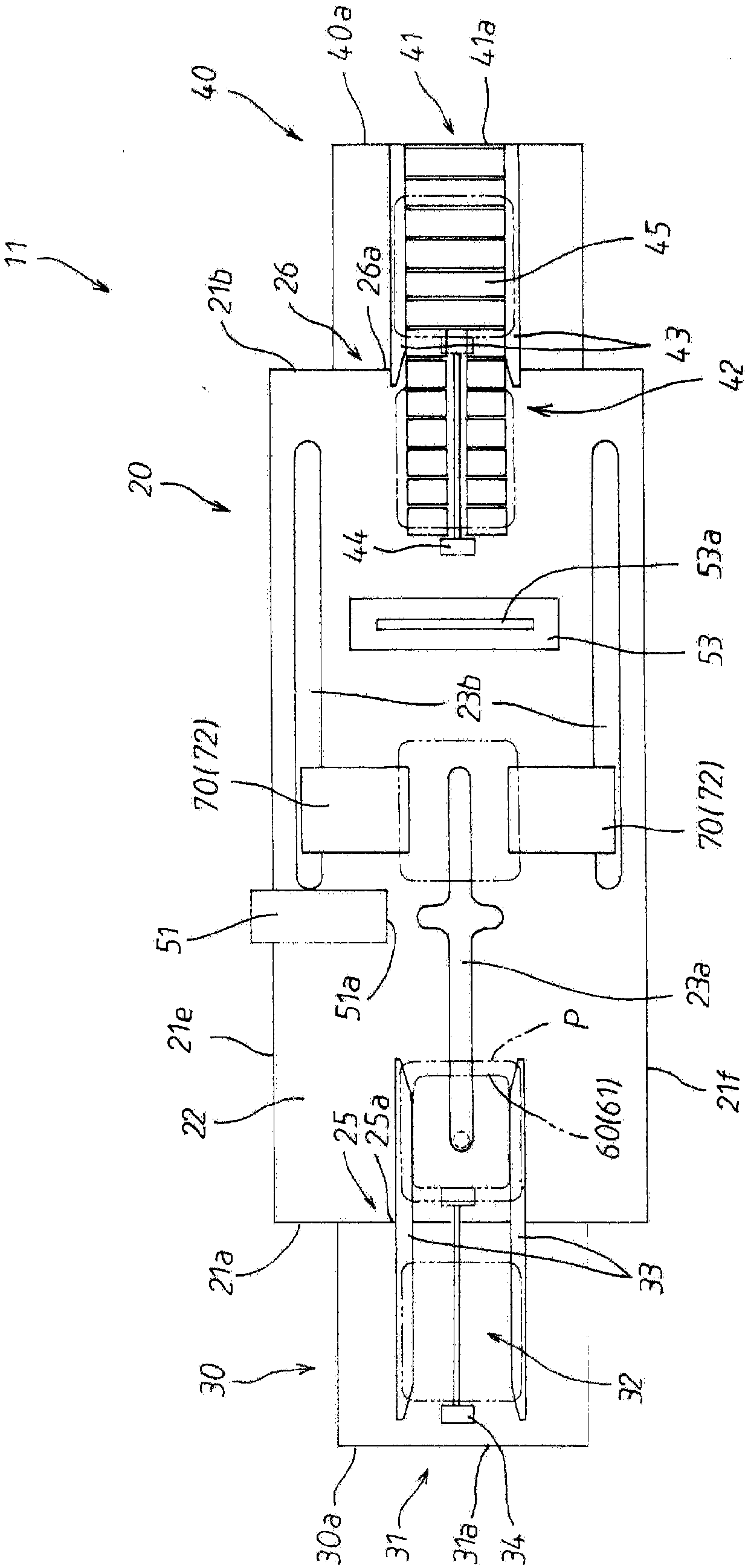
[0070] Next, an electron beam irradiation device according to the first embodiment will be described. image 3 is a schematic plan view showing the electron beam irradiation apparatus according to the first embodiment, Figure 4 It is a schematic front view showing the electron beam irradiation device. Such as image 3 and Figure 4 As shown, the electron beam irradiation device 11 according to the first embodiment is composed of an electron beam irradiation device main body 20 placed on the ground, a transfer box 30 for carrying in and a transfer box for carrying out, which are provided consecutively in front of and behind the main body 20 of the electron beam irradiation device. Box 40 constitutes.

[0071] exist image 3 and Figure 4 Among them, the periphery of the main body 20 of the electron beam irradiation apparatus is covered by outer wall parts 21 (21a to 21f) made of stainless steel metal plates, and the inside thereof is divided into an electron beam irradiat...

no. 2 approach 》

[0136] Next, an electron beam irradiation device according to the second embodiment will be described. Figure 15 is a schematic plan view showing an electron beam irradiation device according to the second embodiment, Figure 16 It is a schematic front view showing the electron beam irradiation device. Such as Figure 15 and Figure 16 As shown, similarly to the above-mentioned first embodiment, the electron beam irradiation apparatus 12 of the present second embodiment consists of an electron beam irradiation apparatus main body 20 placed on the ground and a load-in unit provided in front of and behind the electron beam irradiation apparatus main body 20. It is comprised with the transfer box 30 and the transfer box 40 for carrying out. It should be noted that the respective configurations and structures of the electron beam irradiation apparatus body 20, the transfer box 30 for loading, and the loading device 32, and the transfer box 40 for carrying out and the loading d...

no. 3 approach 》

[0170] Next, an electron beam irradiation device according to the third embodiment will be described. Figure 22 is a schematic plan view showing an electron beam irradiation apparatus according to the third embodiment, Figure 23 It is a schematic front view showing the electron beam irradiation device. Such as Figure 22 and Figure 23 As shown, similarly to the above-mentioned first embodiment, the electron beam irradiation apparatus 13 of the present third embodiment consists of an electron beam irradiation apparatus main body 20 placed on the ground and a load-in unit provided in front of and behind the electron beam irradiation apparatus main body 20. It is comprised with the transfer box 30 and the transfer box 40 for carrying out. It should be noted that the respective configurations and structures of the electron beam irradiation apparatus body 20, the transfer box 30 for carrying in and the carrying-in device 32, and the transfer box 40 for carrying out and the ca...


PUM


Abstract

Provided is an electron beam irradiation device that is capable of uniformly irradiating the entire outer surface of a container with electron beams using small-sized low-energy electron accelerators,and is able to maintain the reliability and safety of the sterilization effect at high levels by sterilizing each part to be sterilized to equal degrees, and is also able to keep the initial costs and maintenance costs of the device low by reducing the costs of the electron accelerators and extending the usage limit (service life) of the electron accelerators. When the side surface portions of the container are irradiated with electron beams with the bottom surface portion of the container supported by a support means, the position of the container is moved by the support means so that the distances between the side surface portions of the container and irradiation windows of the electron accelerators are substantially equal. Next, when an upper surface portion and the bottom surface portion of the container are irradiated with electron beams with the side surface portions of the container held by a holding means, the position of the container is moved by the holding means so that thedistances between the upper surface portion and the bottom surface portion of the container and the irradiation windows of the electron accelerators are substantially equal.

Description

technical field [0001] The present invention relates to an electron beam irradiation device for sterilizing the outer surface of a package containing sterilized articles by electron beam irradiation and transporting the sterilized package to a working room in a sterile environment. Background technique [0002] Prefilled syringes, prefilled vials, etc. that are prefilled with pharmaceuticals are manufactured for the convenience of medical sites. The work of filling the above-mentioned syringes, vials, etc. with pharmaceuticals is performed in a filling work room (hereinafter referred to as "sterile work room") under an aseptic environment. The syringes, medicine bottles, and the like used in this work are small items, and a large number of them need to be handled. Therefore, these syringes, vials, etc. are sterilized by gamma ray irradiation, electron beam irradiation, EOG (ethylene oxide gas) etc. at each manufacturing stage, and are packaged in a predetermined number in a...

Claims


Application Information

Patent Timeline
Patent Type & Authority Applications(China)
IPC IPC(8): A61L2/08A61L2/20G21K5/04G21K5/10A61L101/22
CPCA61L2/08A61L2/20G21K5/04G21K5/10B65B55/08A61L2/087A61L2/26A61L2202/11A61L2202/13A61L2202/24A61L2202/14A61L2202/23
Inventor 川崎康司角田大辅益留纯
Owner AIREX
Why Eureka
Try Eureka