Ice drill bit for warm ice layer drilling

A drill bit and ice layer technology, applied in drill bits, drilling equipment, earthwork drilling, etc., can solve the technical problems that cannot be solved in warm ice layer drilling, complex and difficult accident handling, and increase the cost of polar drilling. Cooling effect, avoiding a lot of sticking, facilitating cooling and carrying ice chips

Inactive Publication Date: 2018-08-10
JILIN UNIV
View PDF5 Cites 0 Cited by
  • Summary
  • Abstract
  • Description
  • Claims
  • Application Information

AI Technical Summary

Problems solved by technology

When drilling with rotary cutting, the heat generated by the cutting of the drill bit can easily melt the ice chips or be in a melted state. These ice chips in a nearly melted state adhere and agglomerate, which is not only difficult to effectively discharge, but also easily adsorbed on the drill bit cutting tool or The local position of the drilling tool hinders the circulation of the drilling fluid and affects the drilling efficiency
These ice chips may even freeze again in some parts of the drill tool, resulting in drill sticking accidents, which not only greatly increases the cost of polar drilling, but also is extremely complicated and difficult to deal with due to the constraints of the polar environment.
Many deep ice core drilling projects, such as the Arctic Greenland Ice Sheet NorthGRIP project, Antarctic Dome C drilling project, etc., have to stop drilling due to the inability to solve the above-mentioned technical problems of drilling in warm ice layers

Method used


Image

  • Ice drill bit for warm ice layer drilling
  • Ice drill bit for warm ice layer drilling
  • Ice drill bit for warm ice layer drilling

Examples


Embodiment 1

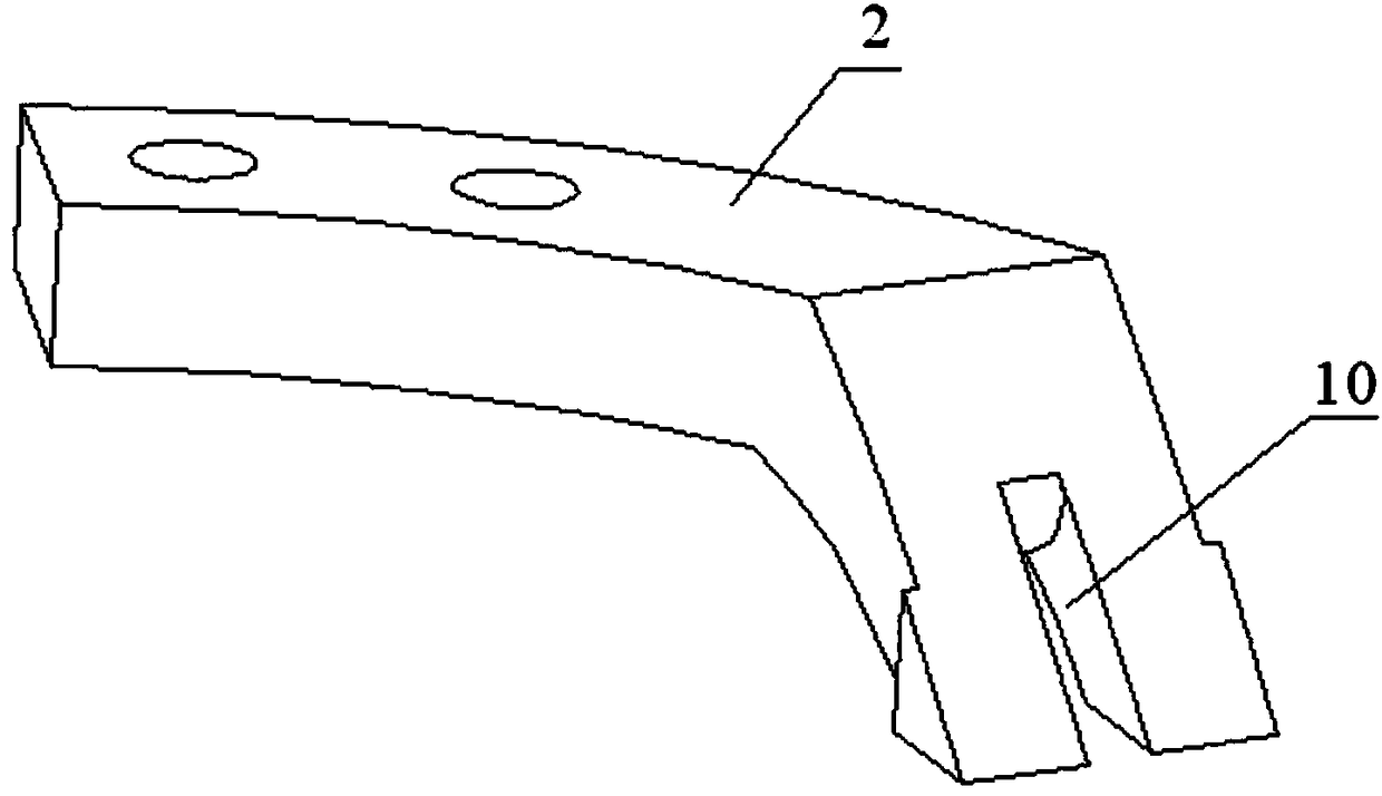
[0024] When the two cutting edges of the special-shaped cutting tool 2 are arranged side by side, a through groove 10 is arranged between the two cutting edges, and the through groove 10 is cylindrical or rectangular.

Embodiment 2

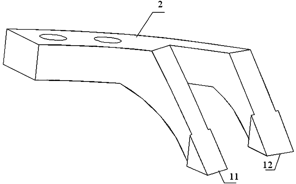
[0026] When the two cutting edges of the special-shaped cutting tool 2 are arranged front and back, the outer diameter of the rear cutting edge 11 is greater than the inner diameter of the front cutting edge 12 .

Embodiment 3

[0028] When the two cutting edges of the special-shaped cutting tool 2 are arranged up and down, the outer diameter of the upper cutting edge 13 is greater than the inner diameter of the lower cutting edge 14 .

[0029] Working principle of the present invention:

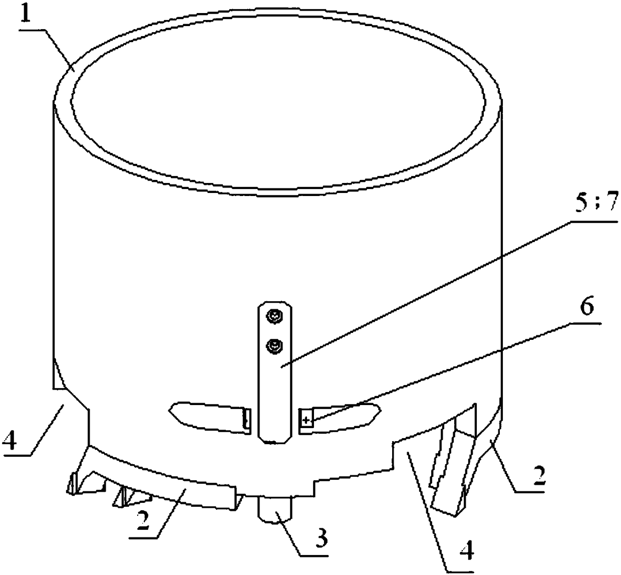
[0030] When the drill body 1 rotates and cuts, the two cutting edges of the special-shaped cutter 2 cut the ice layer respectively to generate ice chips, and the ice chips rise along the two cutting surfaces of the special-shaped cutter 2 respectively. Due to the design of the double cutting edges, it not only reduces The width of a single cutting edge is reduced to effectively reduce the heat generated by rotary cutting, and the amount of ice chips generated by one revolution is greatly reduced. Drilling fluid descends from the annular gap between the drill body 1 and the ice hole wall, and when it flows through the water tank 4 at the bottom of the drill body 1, it cools the special-shaped cutting tool 2 and carri...


PUM


Abstract

The invention discloses a drilling bit of an ice drill for drilling warm ice layer. The drilling bit comprises a drilling bit body, special-shaped cutting tools and pad shoes, wherein the bottom of the drilling bit body is provided with a plurality of water troughs, a channel is formed between the inner cavity and the outer wall of the drilling bit body due to the water troughs, the plurality of special-shaped cutting tools and the pad shoes are fixed on the bottom lip surface of the drilling bit body parallelly, and the bottom of the pad shoes is provided with a plurality of micro-nano bulgesor pits. The drilling bit has the beneficial effect of reducing friction heat of the bottom of the drilling bit. The drilling bit of the ice drill can lower cutting heat, is good for coolinga drilling liquid and carrying flake ice, can effectively prevent a large quantity of flake ice from bonding and gathering, and can drill warm ice layer of the glacier safely and rapidly.

Description

technical field [0001] The invention relates to an ice drill bit, in particular to an ice drill bit for drilling into warm ice layers. Background technique [0002] Currently, the polar ice caps account for about 10% of the global land area, and their natural environment is of great value to human beings. Polar ice caps and glaciers contain ancient ice layers that have accumulated in an orderly manner with snowflakes falling for millions of years. The dust particles, soluble chemicals and gases contained in ice are important for studying global climate change and predicting future climate and environmental changes. is of great significance. All countries in the world are competing to carry out polar deep ice core drilling projects in order to obtain high-quality ice cores with a long history. However, polar drilling practices have shown that there is a region of warm ice at the base of the ice sheet. Under the action of the base ground temperature and the pressure of the ...

Claims


Application Information

Patent Timeline
Patent Type & Authority Patents(China)
IPC IPC(8): E21B10/43E21B10/60E21B10/02E21B25/10
Inventor 曹品鲁刘苗苗陈宝义陈卓赵齐王如生范晓鹏张楠杨阳
Owner JILIN UNIV
Why Eureka
Try Eureka