Part for clock movement

A technology for clock components and clock movements, which is applied in the fields of non-magnetic clock components, fork shafts, escapement pinion shafts, and pendulum shafts, can solve the problems of expensive alloys, difficult chip removal machining, high cost, etc.

Active Publication Date: 2018-01-26
NIVAROX FAR
View PDF8 Cites 0 Cited by
  • Summary
  • Abstract
  • Description
  • Claims
  • Application Information

AI Technical Summary

Problems solved by technology

However, these alloys may show difficulty in chip removal machining
Furthermore,

Method used


Image

  • Part for clock movement
  • Part for clock movement

Examples


Embodiment Construction

[0034] In this specification, the term "non-magnetic" refers to a paramagnetic or diamagnetic or antiferromagnetic material having a magnetic permeability lower than or equal to 1.01.

[0035] The term "dedusting machining" refers to any forming operation by removing material intended to impart dimensions and surface conditions to components within given tolerances. Such operations are for example bar turning, milling or any other process known to a person skilled in the art.

[0036] The present invention relates to a component for a timepiece movement, and in particular to a non-magnetic timepiece component, such as a pivoting arbor, for a mechanical timepiece movement.

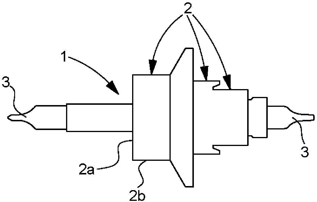
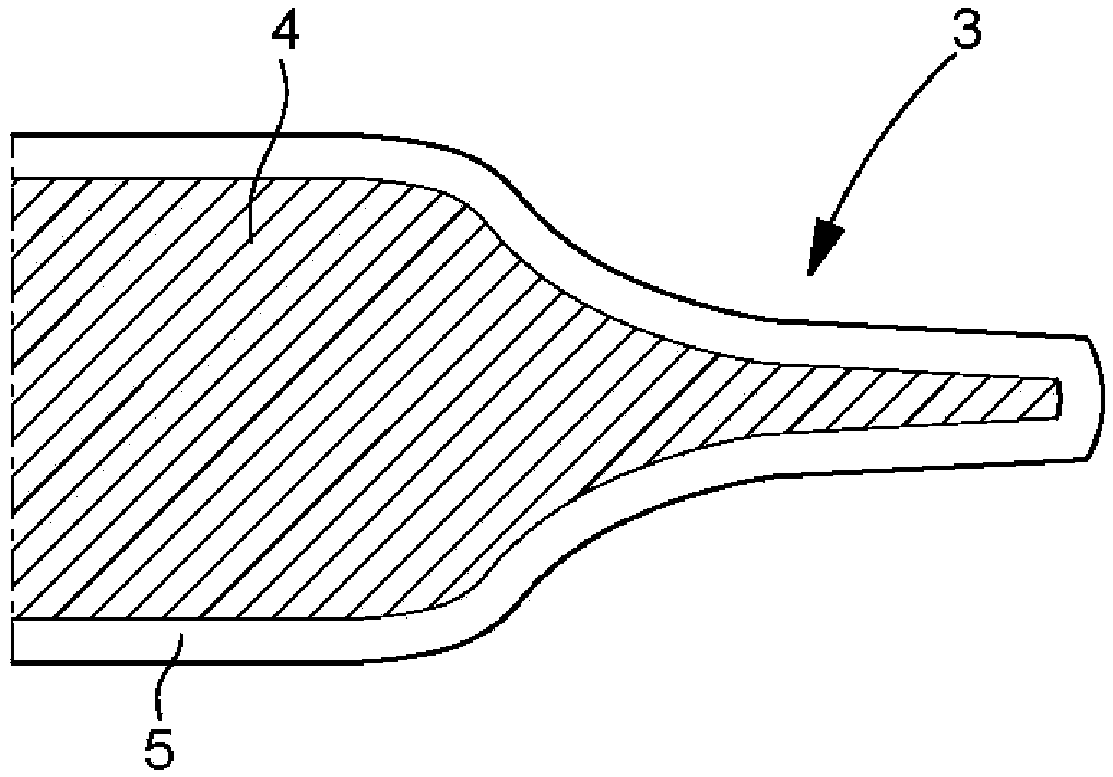
[0037] The invention will be described below with reference to the application of a non-magnetic balance shaft 1 . Of course, other types of timepiece pivot arbors are also conceivable, such as a timepiece wheel set arbor, typically an escapement pinion or a fork. Such a component has a body with a diamet...


PUM


Abstract

The invention relates to a watch component (1) comprising at least one part (3) machined by chip removal. Said part (3) is made of a non-magnetic copper alloy in order to limit its sensitivity to magnetic fields, said copper alloy comprising, by weight, between 10% and 20% of Ni, between 6% and 12% of Sn, X% d additional elements, where X is between 0 and 5, and the remainder of Cu. The inventionrelates to the field of watch movements.

Description

technical field [0001] The invention relates to a component for a timepiece movement, and in particular to a non-magnetic timepiece component for a mechanical timepiece movement, and in particular to a non-magnetic balance, fork and escapement pinion. Background technique [0002] The manufacture of a timepiece component comprising at least one part in the form of a turned component (e.g. a timepiece pivot arbor) involves performing a chip-removing machining operation (e.g. a bar turning operation) on a hardenable steel bar to define different working surfaces (bearing surfaces, shoulders, pivots, etc.) and then subjecting the machined timepiece components to a heat treatment operation comprising at least one hardening operation to increase the hardness of said components and to increase the toughness of the arbor one or more tempering operations. In the case of a pivoted mandrel, the heat treatment operation may be followed by an operation of rolling the pivot of the mandr...

Claims


Application Information

Patent Timeline
IPC IPC(8): G04B15/14G04B31/004
CPCG04B13/026G04B1/16G04B15/14G04B13/02G04B17/32G04B43/007G04B29/00G04B13/022
Inventor C·沙邦V·费伊M·韦拉尔多
Owner NIVAROX FAR
Why Eureka
Try Eureka