Building reserved steel bar cut off device

A technology for reserving steel bars and cutting devices, which is applied in the field of building construction, can solve the problems of uneven stress on steel bars, variable heights, uncontrollable arms, etc., and achieves the effects of improving uniformity, simple structure and improving cutting efficiency.

Inactive Publication Date: 2018-01-30
湖北金丰建筑工程有限公司
View PDF7 Cites 0 Cited by
  • Summary
  • Abstract
  • Description
  • Claims
  • Application Information

AI Technical Summary

Problems solved by technology

[0002] At present, in the field of building construction, it is often necessary to use steel bars to strengthen the strength of the building. Usually, during the construction of the main structure, the construction workers will pre-embed the secondary structural steel bars that need to be reserved in advance, so as to prepare the required steel bars in advance for the subsequent construction process. The steel bars are set well, because the length of the reserved steel bars required for the follow-up operation cannot be accurately determined, in order to ensure the use requirements, the length of the reserved steel bars is usually longer, and the steel bars are cut according to the follow-up needs. The traditional way of cutting steel bars is to operate The personnel perform the cutting operation through the vise, clamp the jaws at the predetermined cutting position, and use both hands to cut off the steel bar. During the operation, there is a high requirement for the operator's arm strength. Long-term operation will consume a lot of physical strength for the operator. When the operator When physical exertion is high, the arm cannot control the cut-off position of the vise, resulting in a deviation in the cut-off length...

Method used


Image

  • Building reserved steel bar cut off device
  • Building reserved steel bar cut off device
  • Building reserved steel bar cut off device

Examples


Embodiment Construction

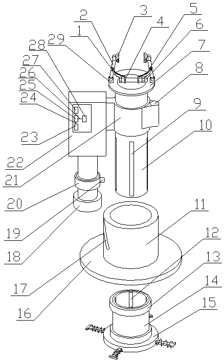
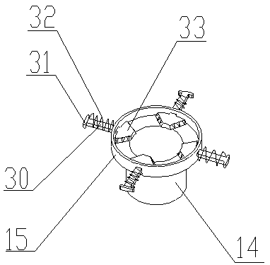
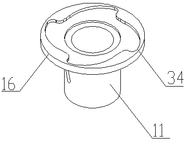
[0031] A device for cutting reserved steel bars for construction in the present invention is realized in this way. When using, when cutting the reserved steel bars, firstly, the fixed cylinder (10) is sleeved on the reserved steel bars, and the rotating disc (16) and The cutting position of the steel bar is corresponding, and then by tightening the bolts, the two pressure blocks (3) are pressed on both sides of the steel bar; the driving motor (22) drives the fixed gear (18) to rotate, and the fixed gear (18) drives the gear sleeve ( 11) Turn, the gear sleeve (11) drives the rotating disc (16) to rotate, the rotating disc (16) drives the rotating groove (34) to rotate, the rotating groove (34) and the four connecting plates rotate relative to each other, and one end of the connecting plate moves from the peak When turning to the trough, the four connecting plates respectively drive the connected cutters (33) to shrink, the springs (32) on the connecting plates are compressed, a...


PUM


Abstract

The invention relates to a building reserved steel bar cut off device, and discloses a device which sleeves a reserved steel bar and cuts off the reserved steel bar through combined action of cuttingand pull up force of a cutter. The device is characterized in that multiple sliding grooves are formed in the outer side of a fixed tube at equal intervals, a connected sleeve sleeves one end of the fixed tube, multiple guide blocks are arranged on the inner wall of the connecting sleeve at equal intervals and each arranged at one end of the corresponding sliding groove, the two ends of a gear sleeve are arranged on the connecting sleeve through fixed bearings, a guide groove is formed in the outer side of the gear sleeve and shaped like an arc, the height is decreased gradually from one end to another end, a rotary disc sleeves one end of the gear sleeve, a rotating groove is formed in the bottom of the rotary disc, a cutter head is arranged at one end of the connecting sleeve and arranged in the rotating groove, four through holes are formed in the cutter head, four sliding plates are arranged, one end of each sliding plate is arranged in a corresponding wave peak of the rotating groove, a sliding block is arranged at one end of each sliding plate, and the cut off efficiency of the reserved steel bar can be effectively improved.

Description

technical field [0001] The invention relates to a device for cutting reserved steel bars for buildings, and relates to a device for cutting reserved steel bars used in building construction, belonging to the field of building construction. In particular, it relates to a device which is set on the reserved steel bar and cuts off the reserved steel bar through the combined action of the cutting of the cutter and the upward pulling force. Background technique [0002] At present, in the field of building construction, it is often necessary to use steel bars to strengthen the strength of the building. Usually, during the construction of the main structure, the construction workers will pre-embed the secondary structural steel bars that need to be reserved in advance, so as to prepare the required steel bars in advance for the subsequent construction process. The steel bars are set well, because the length of the reserved steel bars required for the follow-up operation cannot be ...

Claims


Application Information

Patent Timeline
IPC IPC(8): B21F11/00
Inventor 不公告发明人
Owner 湖北金丰建筑工程有限公司
Why Eureka
Try Eureka