Channel intermittent water supplying device

A water supply device and channel technology, applied in watering devices, irrigation pipelines, climate change adaptation, etc., can solve the problems of water waste in the control room, easy operation failure, large irrigation flow, etc., to achieve large irrigation uniformity and save materials , connect the simple effect

Pending Publication Date: 2018-02-02
FARMLAND IRRIGATION RES INST CHINESE ACAD OF AGRI SCI
View PDF3 Cites 15 Cited by
  • Summary
  • Abstract
  • Description
  • Claims
  • Application Information

AI Technical Summary

Problems solved by technology

[0006] For another example, U.S. Application No. 5782578 discloses a "hydraulic timed irrigation device". Its shortcoming is the same as that of the Chinese patent authorization announcement No. CN103444495B. huge
[0007] Another example is Chen Jun's master's thesis "Research on Canal Irrigation Surge Automatic Irrigation Equipment", which was published on May 20, 2007. Although the canal intermittent water supply has been realized, it is necessary to build a control pool on one side of the canal, occupying farmland, and the device is complicated, the operation is prone to failure, and the water in the control room is wasted through the siphon

Method used


Image

  • Channel intermittent water supplying device
  • Channel intermittent water supplying device
  • Channel intermittent water supplying device

Examples


Embodiment 1

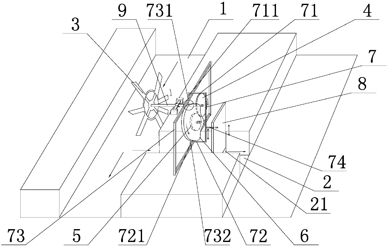
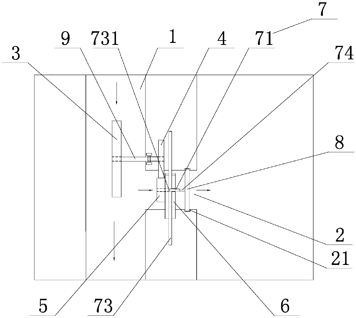
[0026] see Figure 1-4 Shown, a kind of channel intermittent water supply device, it comprises main channel 1, branch channel 2, water wheel 3, driving gear 4, driven gear 5, cam 6, follower 7, gate 8 and connecting shaft 9;

[0027] The branch water channel 2 is opened on the side wall of the main water channel 1, and the water wheel 3 is rotatably suspended above the bottom of the main water channel 1. The water wheel 3 is connected with the driving gear 4 through the connecting shaft 9, and the driving gear 4 and the driven gear 5 meshes, the driven gear 5 is concentrically connected with the cam 6, the gate 8 slides and fits in the chute 21 on the side wall of the branch channel 2, and the gate 8 cooperates with the cam 6 through the follower 7.

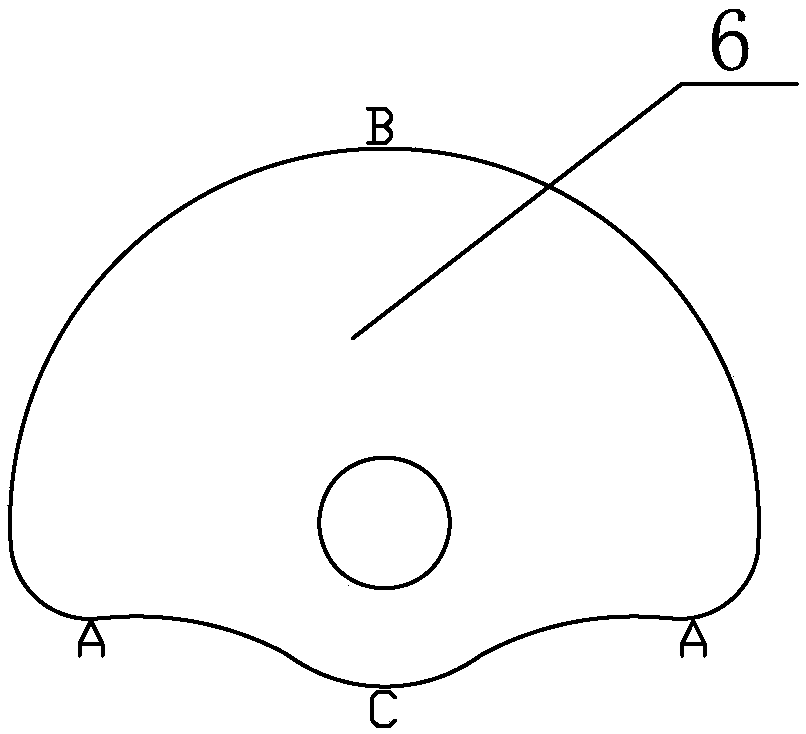
[0028] Described cam 6 is disc cam.

[0029] The follower 7 is a top follower.

[0030] The top follower is a horizontal "П" type structure, and the front end of the upper short arm 71 is bent downward to be provided with an up...

Embodiment 2

[0033] see Figure 5-6 As shown, a channel intermittent water supply device is different from Embodiment 1 in that the follower 61 is a roller follower.

[0034] The roller follower is a horizontal "П" type structure, and the front end of the upper short arm 71 is bent downward to be provided with an upper sliding shaft 711, and the front end of the upper sliding shaft 711 is provided with a roller, which is connected with the cam 6 The side wall of the lower short arm 72 is bent downwards to provide a lower sliding shaft 721. The upper sliding shaft 711 and the lower sliding shaft 721 are respectively slidably sleeved in the upper bushing 731 and the lower bushing 732 of the rectangular frame 73. , the rectangular frame 73 with the upper bushing 731 and the lower bushing 732 is fixed on the ground on both sides of the branch water channel 2 through the supporting legs, and the bottom of the horizontally placed "П" type structure roller follower protrudes horizontally. The co...


PUM


Abstract

The invention relates to a channel intermittent water supplying device. The channel intermittent water supplying device comprises a main water channel, a branch water channel, a water wheel, a drivinggear, a driven gear, a cam, a follower, a gate and a connecting shaft; the water wheel is arranged above the channel bottom of the main water channel in a suspended mode and is connected with the driving gear through the connecting shaft, the driving gear is engaged with the driven gear, and the driven gear is connected with the cam in a concentric shaft mode; and the gate is in slidable fit withthe interior of a sliding groove in the side wall of the branch water channel and is in linkage fit with the cam through the follower. Compared with traditional ground irrigation, the channel intermittent water supplying device is large in irrigation uniformity and good in water-saving effect; compared with drip irrigation and sprinkling irrigation, the channel intermittent water supplying deviceis small in investment; and the device controls irrigation conveniently, connection is simple, no occupation of additional land is not required, materials are saved, and operation is easy.

Description

technical field [0001] The invention relates to the technical field of agricultural water and soil engineering, in particular to a canal intermittent water supply device. Background technique [0002] Intermittent irrigation is mainly used in border irrigation or small furrow irrigation. Intermittent irrigation technology is a water-saving surface irrigation technology that periodically supplies irrigation water to furrows intermittently until the water flow reaches the end of the furrow (furrow), also known as gushing irrigation technology. Self-gravity and soil capillary force; the entire irrigation process is composed of several water supply and water stop cycles. Intermittent irrigation causes the field soil to dry and wet alternately in the length of the previous cycle of irrigation, and the structural properties of the surface soil change accordingly to form a dense layer. , the infiltration capacity of irrigation water flow in the ditch (furrow) soil wet section is r...

Claims


Application Information

Patent Timeline
Patent Type & Authority Applications(China)
IPC IPC(8): E02B13/00E02B13/02A01G25/16
CPCA01G25/16E02B13/00E02B13/02Y02A40/22
Inventor 温季姜新郭树龙
Owner FARMLAND IRRIGATION RES INST CHINESE ACAD OF AGRI SCI
Why Eureka
Try Eureka