Optical system with visibility adjustment function

An optical system and dioptric adjustment technology, applied in the field of optical systems, can solve the problems of increasing the weight and complexity of the optical system, avoid design and adjustment, and improve the image quality

Inactive Publication Date: 2018-02-02
德伽智能光电(镇江)有限公司 +1
View PDF9 Cites 8 Cited by
  • Summary
  • Abstract
  • Description
  • Claims
  • Application Information

AI Technical Summary

Problems solved by technology

This adjustment method needs to design a precise displacement structure for image plane adjustment, and has enough adjustment space, which increases the weight and complexity of the optical system in front of the eye

Method used


Image

  • Optical system with visibility adjustment function
  • Optical system with visibility adjustment function
  • Optical system with visibility adjustment function

Examples


Embodiment 1

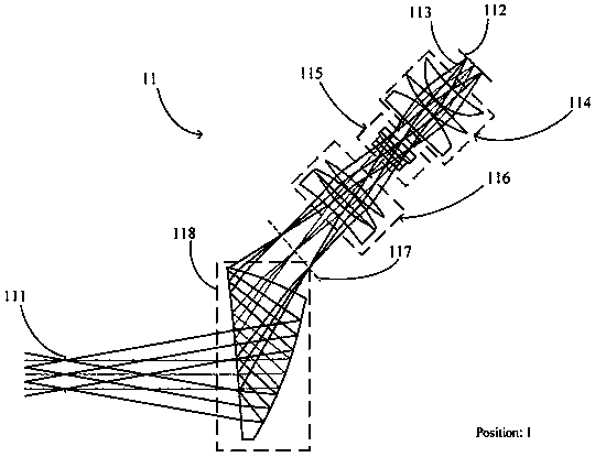
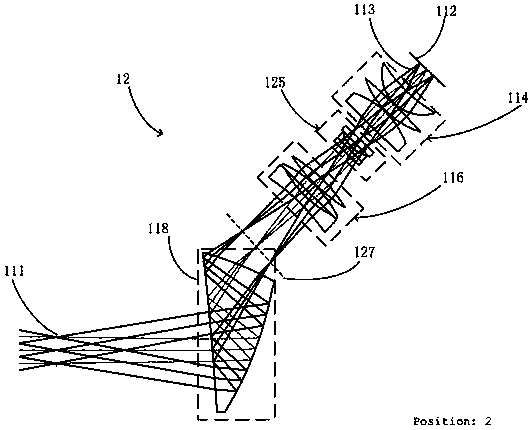
[0039] Such as figure 2 As shown in FIG. 1 , it shows an optical path diagram of an optical imaging system with a diopter adjustment function in a state of +0D diopter, and the optical imaging system is suitable for a head-mounted display. The optical imaging system includes an image source 112 , a first lens group 114 , a liquid lens 115 , a second lens group 116 , and a free-form surface prism 118 .

[0040]Wherein, the image source 112 , the first lens group 114 , the liquid lens 115 and the second lens group 116 are coaxially arranged. The image light 113 emitted by the image source 112 sequentially passes through the first lens group 114 , the liquid lens 115 and the second lens group 116 , forming an intermediate image plane 117 between the second lens group 116 and the free-form surface prism 118 . The free-form prism 118 and the second lens group 116 are placed at predetermined relative positions and angles, so that the image light 113 can be incident on the upper su...

Embodiment 2

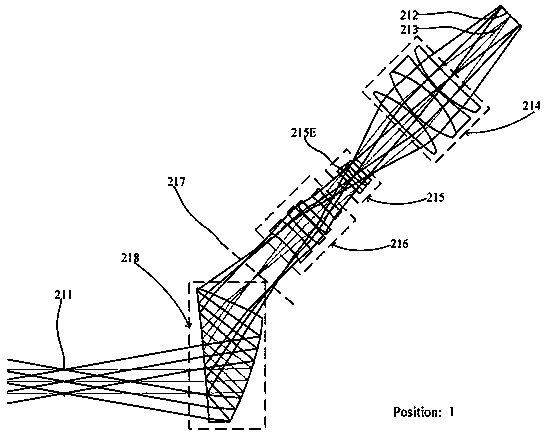
[0057] Figure 10 , Figure 11 , Figure 12 They are the optical path diagrams of the optical system in the three diopter states of +0D, -2D, and -8D in Embodiment 2 of the present invention, which are the same as Embodiment 1, including an image source 212, a first lens group 214, a liquid lens 215, and a first lens group 215. Two lens groups 216, and free-form surface prism 218, differ from Embodiment 1 in that the first lens group 214 is made up of two spherical lenses 24A, 24C and a doublet lens 24B, and the second lens group 216 is made up of four spherical lenses 26A , 26B, 26C, and 26D; in this example, the free-form prism includes two free-form surfaces.

[0058] Similarly, a compensating prism 219 can also be added to the right side of the free-form surface prism 218. The right side surface of the free-form surface prism 218 is coated with a spectroscopic film layer, a part of the light is reflected by the film layer, and the other part is transmitted through the f...

Embodiment 3

[0068] Figure 13 It is the optical path diagram of the optical system in the +0D diopter state of Embodiment 3 of the present invention, which is the same as Embodiment 2, including an image source 312, a first lens group 314, a liquid lens 315, a second lens group 316, and a free-form surface prism 318. Different from Embodiments 1 and 2, a mirror 3111 is placed between the first lens group 314 and the liquid lens 315 to receive the image light 313 transmitted from the first lens group 314 and reflect the image light 313 to the liquid lens 315, so that the first lens group 314, the liquid lens 315 and the second lens group 316 are arranged in a reflective form. Such a reentrant optical path design can further shorten the space occupied by the optical elements required to form the intermediate image plane.

[0069] Similarly, a compensating prism 319 can also be added to the right side of the free-form surface prism 318. The right side surface of the free-form surface pris...


PUM


Abstract

The invention provides an optical system with a visibility adjustment function. The system comprises an image source for generating image light, a first lens group, a liquid lens with a zooming function, a second lens group, and a free-form-surface prism. The image light sequentially passes through the above optical members and reaches an exit pupil plane to enter a human eye to carry out imaging,and the visibility adjustment function is realized. The visibility adjustment requirement of a wearer is satisfied, and the wearing convenience and comfort are improved. The liquid lens and the likeare used to realize visibility adjustment, the design and adjustment of a complex axial mechanical zoom structure are avoided, combined with a visual magnification element of a free-form-surface prismmode, in the design of an optical imaging system, an optical imaging system with small distortion, high image quality and a compact structure can be provided, and the assembly error of the optical system is reduced.

Description

technical field [0001] The invention relates to an optical system with diopter adjustment function, in particular to an off-axis visual optical system with diopter adjustment function. Background technique [0002] The head-mounted display device magnifies the image of the image source through the visual optical system and presents it in front of the user's eyes, presenting different visual effects according to different applications, such as 3D display, augmented reality applications, etc., and because the image only enters the user's eyes , Compared with traditional displays, it has better privacy. With the rapid development of virtual reality and augmented reality, head-mounted display devices have received more and more attention due to their huge market value and development potential. [0003] The transmissive Near Eye Display (NED) system is a small photoelectric display device that is worn in front of the user's eyes and provides the wearer with a visual virtual ima...

Claims


Application Information

Patent Timeline
Patent Type & Authority Applications(China)
IPC IPC(8): G02B27/01
CPCG02B27/0101G02B27/0172G02B2027/0129
Inventor 程德文王其为
Owner 德伽智能光电(镇江)有限公司
Why Eureka
Try Eureka