Contactor power saver

A technology of power saver and contactor, which is applied in the direction of relays, circuits, electrical components, etc., can solve the problem of low power factor and achieve the effect of simple circuit and low cost

Active Publication Date: 2018-02-02
SHENZHEN NANYUN MICROELECTRONICS CO LTD +1
View PDF7 Cites 7 Cited by
  • Summary
  • Abstract
  • Description
  • Claims
  • Application Information

AI Technical Summary

Problems solved by technology

For example, in the patent application number 200510029373.2, the electromagnetic coil is powered in the form of a pulse, so that the electromagnetic coil works with a constant small current; using this method will not only generate a

Method used


Image

  • Contactor power saver
  • Contactor power saver
  • Contactor power saver

Examples


no. 1 example

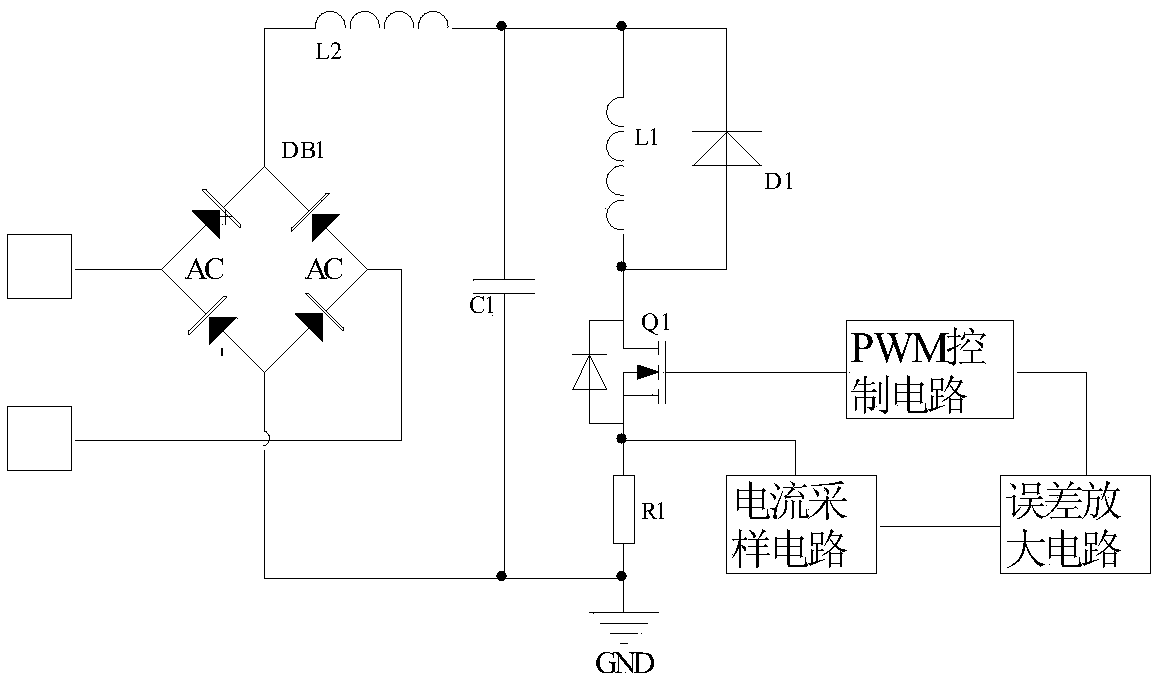
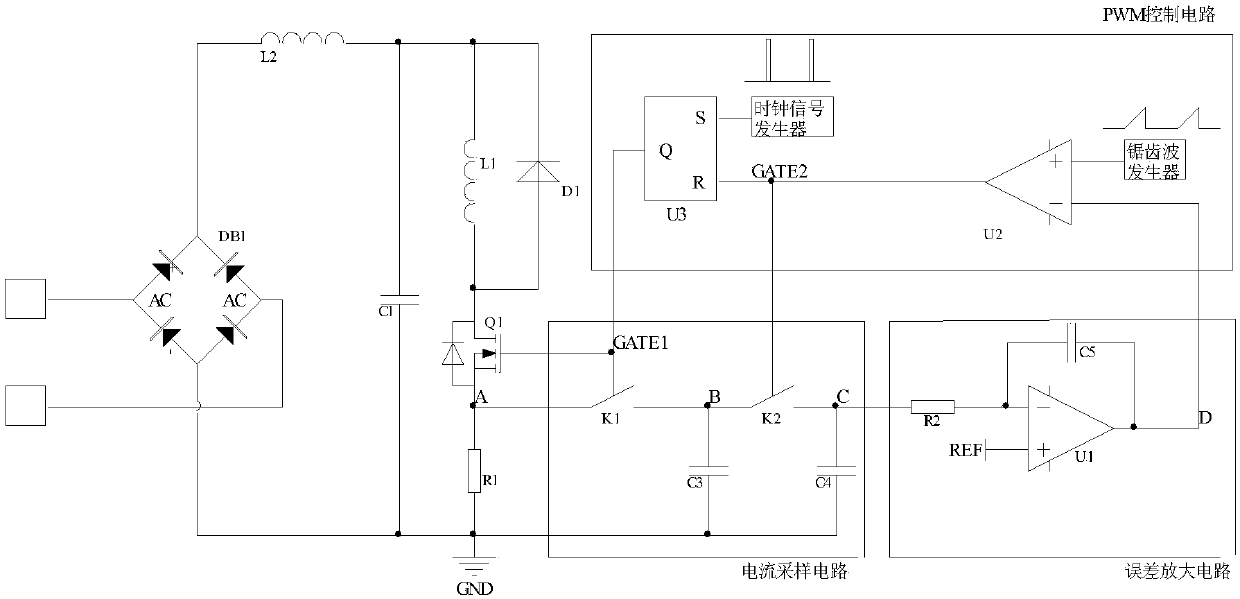
[0028] A contactor power saver comprises a main power circuit, a current sampling circuit, an error amplifier circuit and a PWM control circuit. The current sampling circuit samples the voltage signal of the main power circuit, and outputs a current sampling signal; the error amplifier circuit compares the current sampling signal with a reference voltage signal REF, and outputs an error voltage signal; the PWM control circuit detects The error voltage signal outputs a driving signal GATE1 with a constant frequency and a duty cycle proportional to the error voltage signal, to drive the switch tube in the main power circuit to turn on and off.

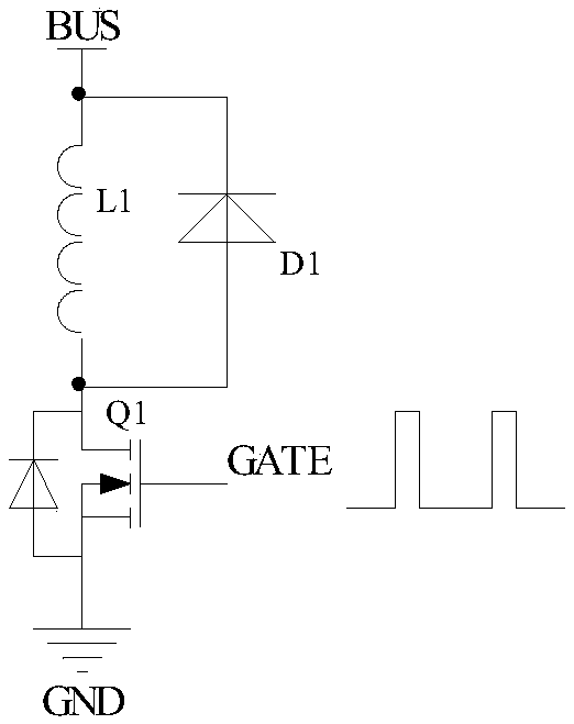
[0029] The main power circuit is composed of rectifier bridge DB1, inductor L2, capacitor C1, contactor coil L1, diode D1, N-MOS transistor Q1 and resistor R1. The two AC input ends of DB1 are respectively connected to the AC power, the rectified positive output end of DB1 is connected to one end of L2, and the rectified negative output ...


PUM


Abstract

The invention provides a contactor power saver, which comprises a main power circuit, a current sampling circuit, an error amplifying circuit and a PWM control circuit. The current sampling circuit samples a voltage signal of the main power circuit and outputs a current sampling signal. The error amplifying circuit compares the current sampling signal with a reference voltage and outputs an errorvoltage signal. The PWM control circuit detects the error voltage signal, outputs a drive signal with a constant frequency and a duty ratio proportional to that of the error voltage signal, and controls the on/off state of a switch tube in the main power circuit. By the invention, the power factor value can be increased to about 0.9V and the current of a contactor coil is constant under the wide-range input voltage. Modules of the control circuit can be integrated, the circuit is simple, and the cost is low.

Description

technical field [0001] The invention relates to the field of AC contactors, in particular to a contactor power saver with power factor correction function. Background technique [0002] The traditional contactor operating system consists of a coil, a static iron core, an armature and a reaction spring. When the contactor coil is energized, a suction force is generated between the static iron core and the armature. When the suction force is greater than the spring reaction force, the armature is attracted to the static iron core until it contacts the static iron core. At this time, the main contact is closed. This process is called suction. combined process. The process in which the coil is continuously energized, the armature is in contact with the static iron core, and the main contacts are in a closed state is called the holding process. When the current in the coil is reduced or interrupted, the suction force of the static iron core to the armature decreases. When the s...

Claims


Application Information

Patent Timeline
IPC IPC(8): H01H47/02
CPCH01H47/02
Inventor 尹向阳苏俊熙
Owner SHENZHEN NANYUN MICROELECTRONICS CO LTD
Why Eureka
Try Eureka