A needle-ring type ionic wind fin cooling device

A technology of heat sink and ion wind, applied in cooling/ventilation/heating renovation, electrical components, electrical equipment structural parts, etc. Advanced problems, to achieve the effect of improving heat exchange performance, simple structure and good working stability

Active Publication Date: 2019-08-09
XI AN JIAOTONG UNIV
View PDF16 Cites 0 Cited by
  • Summary
  • Abstract
  • Description
  • Claims
  • Application Information

AI Technical Summary

Problems solved by technology

[0005] Most of the ion wind devices in the above patents use the ion wind as an external fan to blow the heat source or radiator, which is an additional structure, which will increase the volume of the radiator, and the degree of compactness and integration is not high, and Corresponding design is required during installation and use, which may change the internal structure layout of the original electronic equipment

Method used


Image

  • A needle-ring type ionic wind fin cooling device
  • A needle-ring type ionic wind fin cooling device
  • A needle-ring type ionic wind fin cooling device

Examples


Embodiment Construction

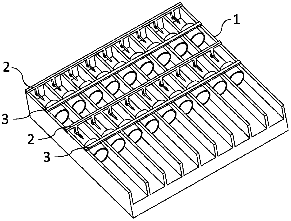
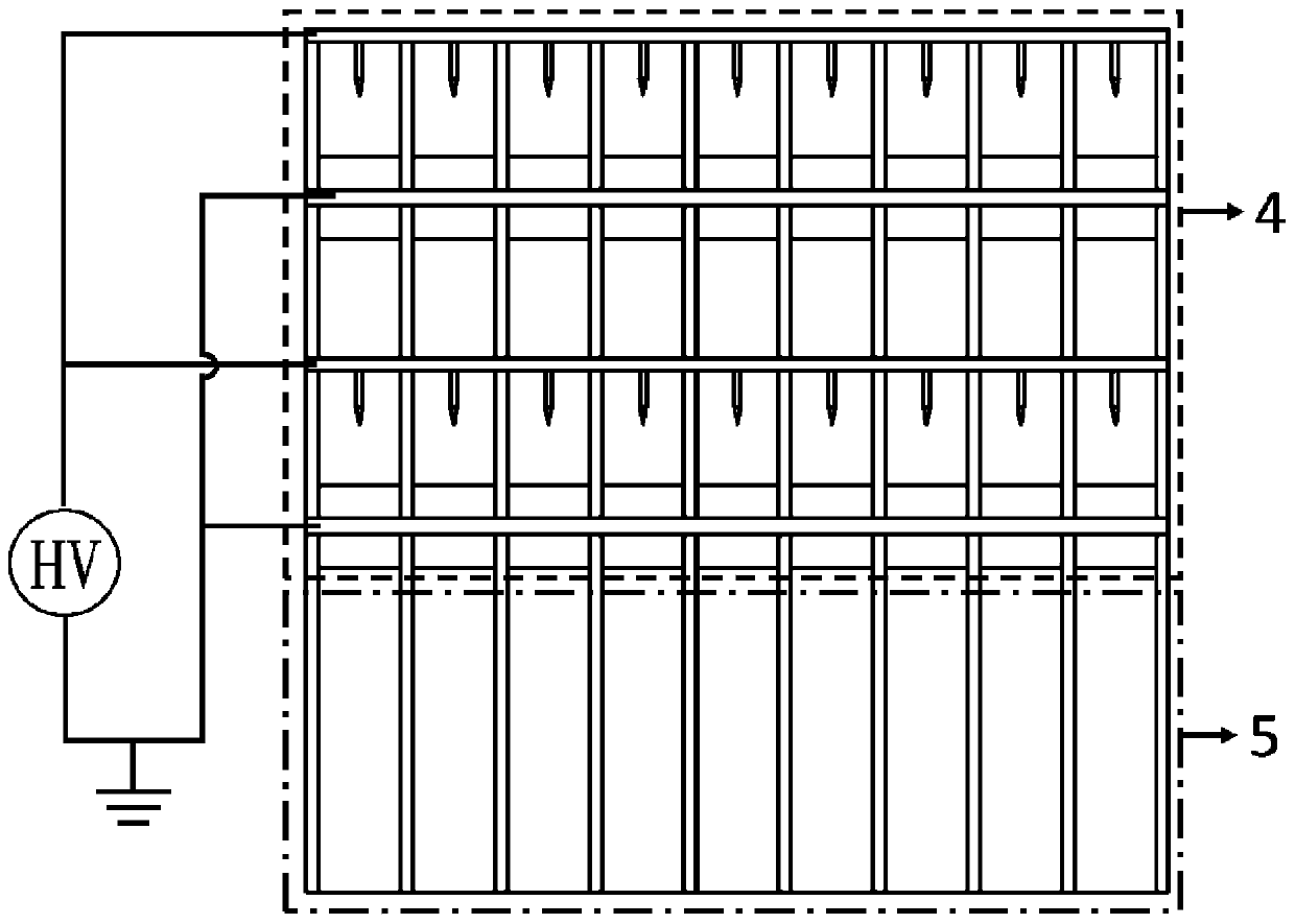
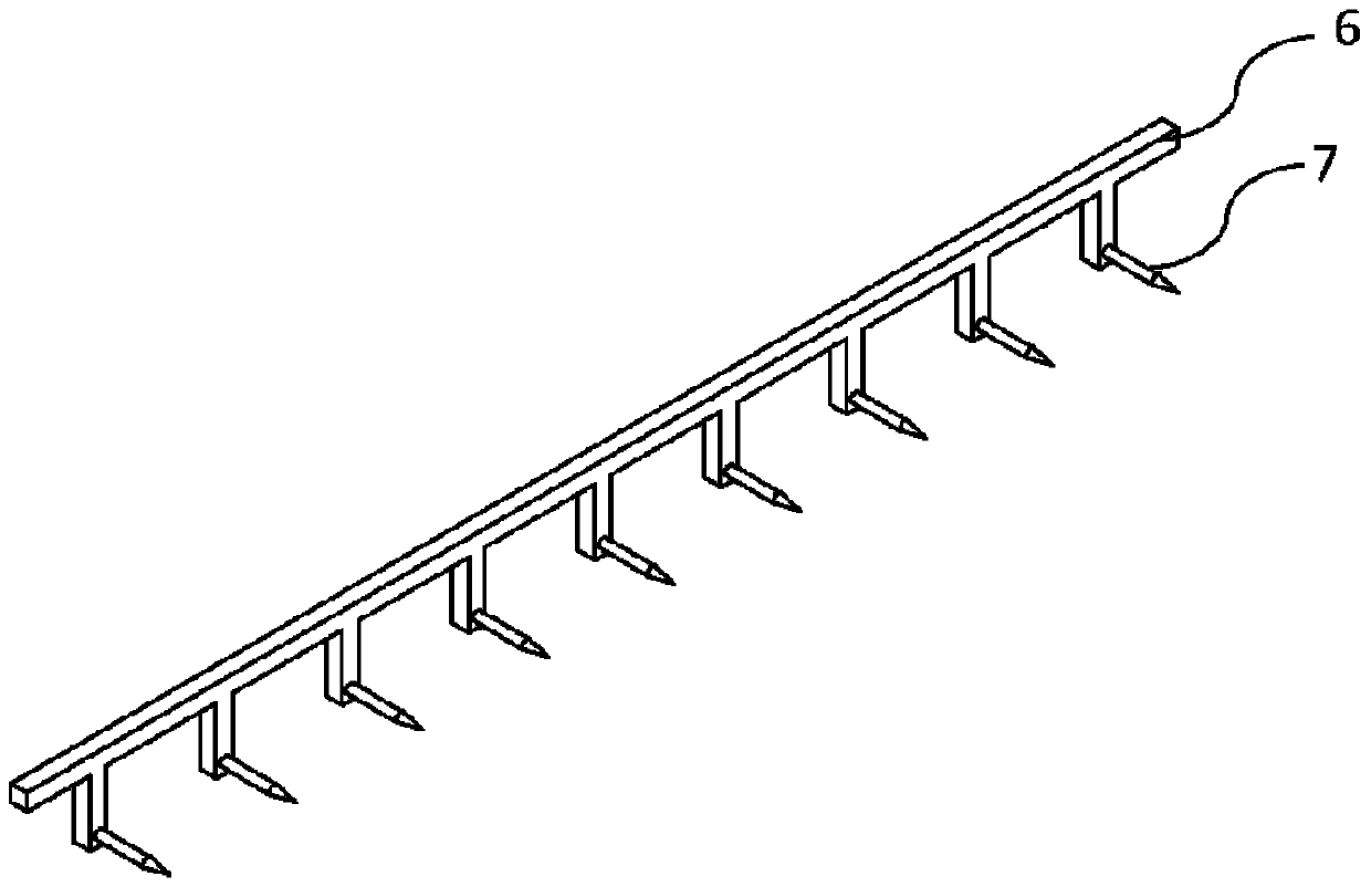
[0027] The present invention will be described in further detail below in conjunction with the accompanying drawings.

[0028] ginseng figure 1 , 3 , 4. The present invention includes radiating fins 1 and several stages of ion wind devices with operating voltages of -6 to -13kV composed of needle electrodes 2 and ring electrodes 3 installed between adjacent fins. The fins of radiating fins 1 The spacing between the sheets is 10-25 mm. The needle electrode 2 is composed of an electrode plate 6 installed on the heat dissipation fin 1 and several tungsten needles 7 connected to the electrode plate 6 and placed between adjacent fins. The ring The electrode 3 is composed of a conductive strip 8 installed on the heat dissipation fin 1 and a number of metal rings 9 connected to the conductive strip 8 and placed between adjacent fins. The tungsten needle 7 of the needle electrode 2 is facing the metal ring 9. The center of the ring 9, the distance between the end of the upper ring e...


PUM


Abstract

The invention relates to the technical field of electronic equipment cooling, and specifically relates to a needle-ring type ion wind fin cooling device. The device has the advantages of simple structure, small size, no noise, no moving parts, low power consumption and the like, and is suitable for enhancing air-side cooling of electronic equipment. According to the device, a needle-ring type ionwind generator is arranged in a cooling fin channel of the electronic equipment, when the ion wind generator is powered on to work, air flow can be produced to cool fins, and the fin cooling efficiency can be effectively improved; in addition, an insulating layer is coated on the cooling fins to prevent a needle from directly discharging to the fins, and the insulation requirements of the electronic equipment can be ensured; and meanwhile, a catalyst layer is also coated on the cooling fins to eliminate ozone generated when the ion wind generator ionizes air.

Description

technical field [0001] The invention relates to a cooling device for electronic equipment, in particular to a pin-ring type ion wind fin cooling device with compact structure and combined with fins. Background technique [0002] With the increase of heat flux emitted by electronic devices, the heat dissipation capacity of some electronic devices using natural convection heat dissipation can no longer meet the heat dissipation requirements. If the heat cannot be discharged in time, it will affect the life and work efficiency of electronic devices. However, if a fan is used for forced convection heat dissipation, in order to meet the heat dissipation requirements, the size of the fan continues to increase, causing the overall volume of the heat dissipation device to be too large, and the fan will generate noise, vibration and other problems during operation, and even damage to moving parts, resulting in The heat sink is not working properly. [0003] The ion wind technology b...

Claims


Application Information

Patent Timeline
Patent Type & Authority Patents(China)
IPC IPC(8): H05K7/20
CPCH05K7/20145H05K7/20172H05K7/20418
Inventor 屈治国曾敏军张剑飞王爽
Owner XI AN JIAOTONG UNIV
Why Eureka
Try Eureka