Anti-splashing device of milling machine cuttings

A technology of anti-splash and milling machine, which is applied in the direction of metal processing machinery parts, maintenance and safety accessories, metal processing equipment, etc., can solve problems such as hidden safety hazards, and achieve the effect of easy collection and good sealing effect

Inactive Publication Date: 2018-02-06
成都立威斯科技有限公司
View PDF0 Cites 3 Cited by
  • Summary
  • Abstract
  • Description
  • Claims
  • Application Information

AI Technical Summary

Problems solved by technology

[0005] The present invention provides a milling machine chip anti-splashing device aiming at the potential safety hazards caused by chips splashing during machining of the existing common milling machine.

Method used


Image

  • Anti-splashing device of milling machine cuttings
  • Anti-splashing device of milling machine cuttings

Examples


Embodiment 1

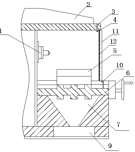
[0023] Such as figure 1 As shown, a chip anti-splash device of a milling machine is installed on a milling machine. The milling machine is equipped with a spindle 1, and a worktable 5 is arranged under the spindle 1, and is characterized in that: the anti-splash device includes the device installed on the spindle 1. The upper beam 2, the gas passage 3 arranged in the beam 2, and a plurality of nozzles 4 vertically installed below the gas passage 3; the beam 2 is a cantilever structure, and the nozzle 4 is away from the main shaft 1 along the beam 2 The air path 3 includes an air inlet connected with a pneumatic pump and a plurality of air outlets arranged along the side of the beam 2 away from the main shaft 1; both sides of the workbench 5 are provided with transparent cutting baffles 11, The upper end of the transparent cutting baffle 11 is in contact with the beam 2. The transparent cutting baffle 11 and the air wall sprayed from the air outlet form a horizontally placed "U"...

Embodiment 2

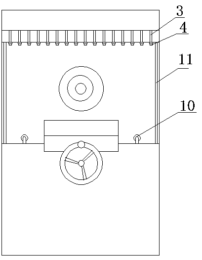
[0028] This embodiment is improved on the basis of embodiment 1, and its improvement lies in: figure 2 As shown, the nozzle 4 and the air outlet are connected by a hose that can change the angle between the nozzle 4 and the air outlet. The angle between the nozzle 4 and the beam 2 can be rotated according to the processing conditions to control the angle formed by the air wall to make the sealing effect better. Good, to meet the needs of different workpieces; the nozzle 4 can also be slightly offset to the direction of the spindle 1, so that the air wall and the worktable 5 form an obtuse angle, so that the cutting is easier to collect and enter the chip box 9. A second group of nozzles 10 connected with the air inlet of the air pump and arranged horizontally is fixedly installed on the rib 6 at one end far away from the main shaft 1; the air jet direction of the second group of nozzles 10 is the direction of the main shaft 1. The gas blown by the second set of nozzles 10 can ...

Embodiment 3

[0030] This embodiment is improved on the basis of embodiment 1, and its improvement lies in: figure 1 As shown, the beam 2 is provided with a second transparent cutting baffle 12 extending vertically downward along the outer edge of the nozzle 4; the second transparent cutting baffle 12 and the outer edge of the beam 2 can be rotatably connected by a rotating shaft, The lower end of the second transparent cutting baffle 12 is in contact with the rib 6. In milling machine processing, the use of air wall anti-splash can not completely block cutting splash, or a larger air pressure and air injection volume are required to achieve a better anti-cutting splash effect, and the air wall air pressure and air injection volume are large, but it is easy to cause gas impact cutting Cause cutting splashes and cause safety hazards. Therefore, the machine tool and the transparent cutting baffle 11 and the second transparent cutting baffle 12 are used to form a sealed anti-cutting splash area...


PUM


Abstract

The invention discloses a chip anti-splash device for a milling machine, which is installed on the milling machine. The milling machine is equipped with a main shaft and a workbench. The anti-splash device includes a beam installed above the main shaft, an air channel arranged in the beam, and A plurality of nozzles installed vertically under the air channel; the beam is a cantilever structure, and the nozzles are installed along the side of the beam away from the main shaft; transparent cutting baffles are arranged on both sides of the workbench, and the transparent cutting baffle The top of the plate is in contact with the beam. In the present invention, nozzles are installed at one end of the beam of the machine tool and transparent cutting baffles are installed on both sides of the workbench, relying on the pressurized air flow ejected from the nozzles and the transparent cutting baffles to form a "U"-shaped anti-cutting and splashing area to seal the working area of ​​the machine tool , to avoid the chips splashing to the outside of the machine tool, causing hidden dangers of safety accidents, and the air wall and transparent cutting baffle will not affect the operator's sight, reducing the impact on processing after adding this device.

Description

Technical field [0001] The invention belongs to the technical field of machine tool equipment, and in particular relates to a chip anti-splash device of a milling machine. Background technique [0002] The milling machine is a wide range of machine tools. On the milling machine, it can process planes (horizontal planes, vertical planes), grooves (keyways, T-slots, dovetail grooves, etc.), gear parts (gears, spline shafts, sprockets), Spiral surface (thread, spiral groove) and various curved surfaces. In addition, it can also be used to process the surface and inner hole of the revolving body and cut off the work. When the milling machine is working, the workpiece is mounted on the worktable or the indexing head and other accessories, and the milling cutter rotates as the main motion, supplemented by the feed motion of the worktable or the milling head, and the workpiece can obtain the required processing surface. Due to the multi-edge intermittent cutting, the productivity of t...

Claims


Application Information

Patent Timeline
Patent Type & Authority Applications(China)
IPC IPC(8): B23Q11/00B23Q11/08
CPCB23Q11/00B23Q11/0067B23Q11/08
Inventor 姚清群
Owner 成都立威斯科技有限公司
Why Eureka
Try Eureka