
Grating measuring device

A grating measurement and grating technology, applied in the direction of measuring devices, optical devices, instruments, etc., can solve the problems of large measurement errors, large size of the light-passing surface of the grating ruler, and high cost, and achieve convenient installation and use, compressed installation space, and size compact effect

Active Publication Date: 2019-08-23
SHANGHAI MICRO ELECTRONICS EQUIP (GRP) CO LTD
View PDF7 Cites 0 Cited by
  • Summary
  • Abstract
  • Description
  • Claims
  • Application Information

AI Technical Summary

Problems solved by technology

Due to the different positions of the measurement point in the X direction and the measurement point in the Y direction when measuring in the horizontal direction, the measurement error is large, and the size of the light-transmitting surface required by the grating ruler is large and the cost is high

Method used


Image

  • Grating measuring device
  • Grating measuring device
  • Grating measuring device

Examples


Embodiment 1

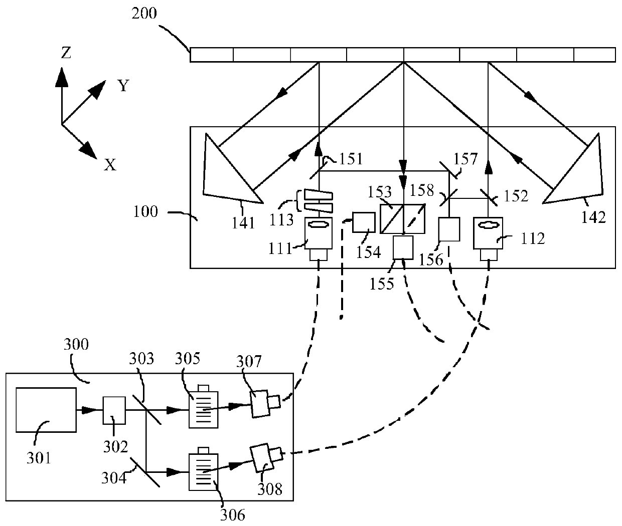
[0059] Such as figure 1 As shown, the grating measuring device of the present embodiment includes:

[0060] A light source module 300, configured to generate two beams of light with different frequencies;

[0061] Grating 200;

[0062] Multiple detectors (not shown in the figure),

[0063] Signal processor (not shown in the figure);

[0064] as well as

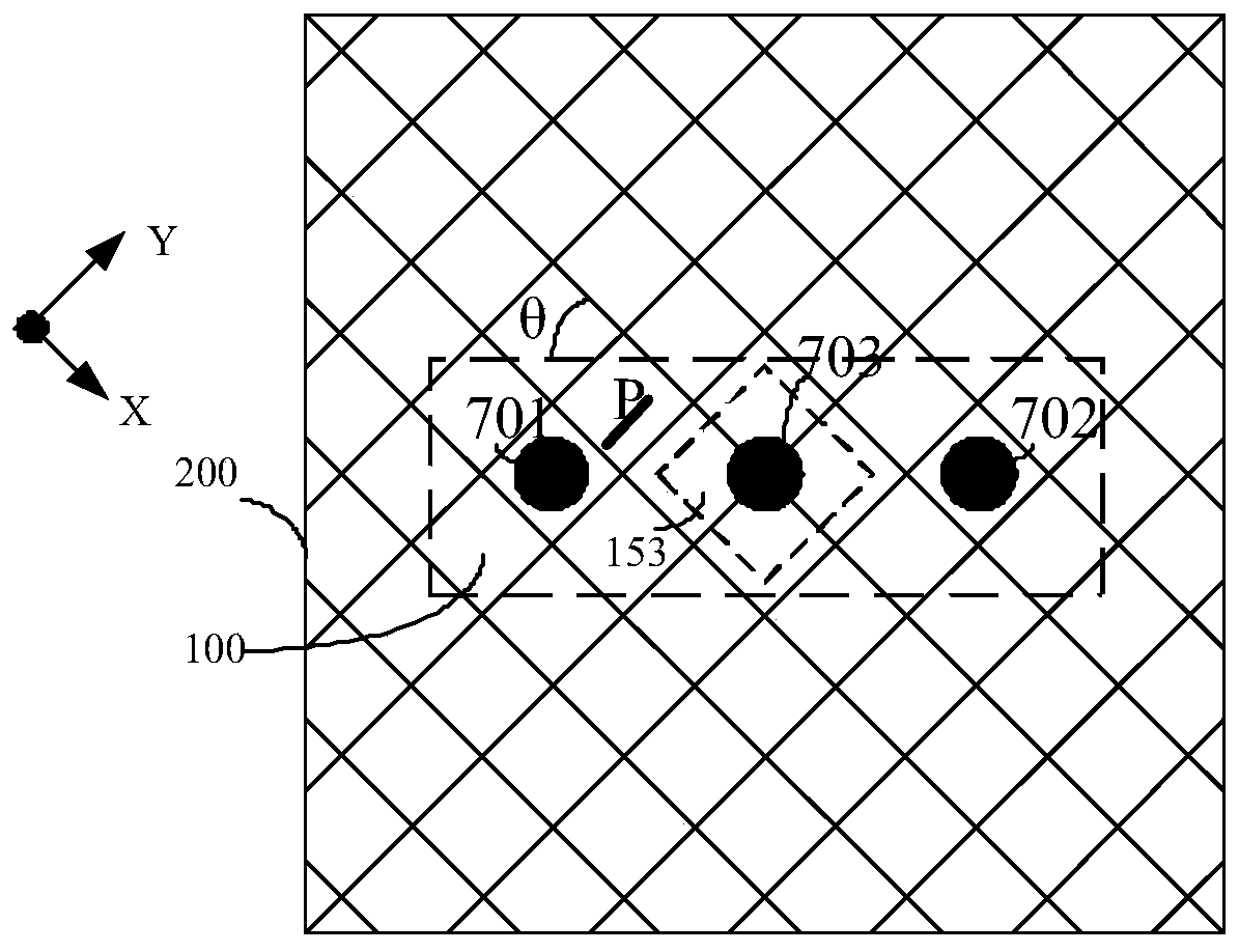
[0065] The grating measurement probe 100 includes a dual-frequency incident light module, a horizontal detection module, a reference detection module and two retroreflectors arranged symmetrically. In this embodiment, the retroreflectors are preferably corner cube prisms 141, 142, wherein , the dual-frequency incident light module is used to receive the two beams and project the two beams onto the surface of the grating 200 and the reference detection module, the two beams are diffracted on the surface of the grating 200, and the diffracted light is projected onto the surface of the grating 200 The corresponding retrorefl...

Embodiment 2

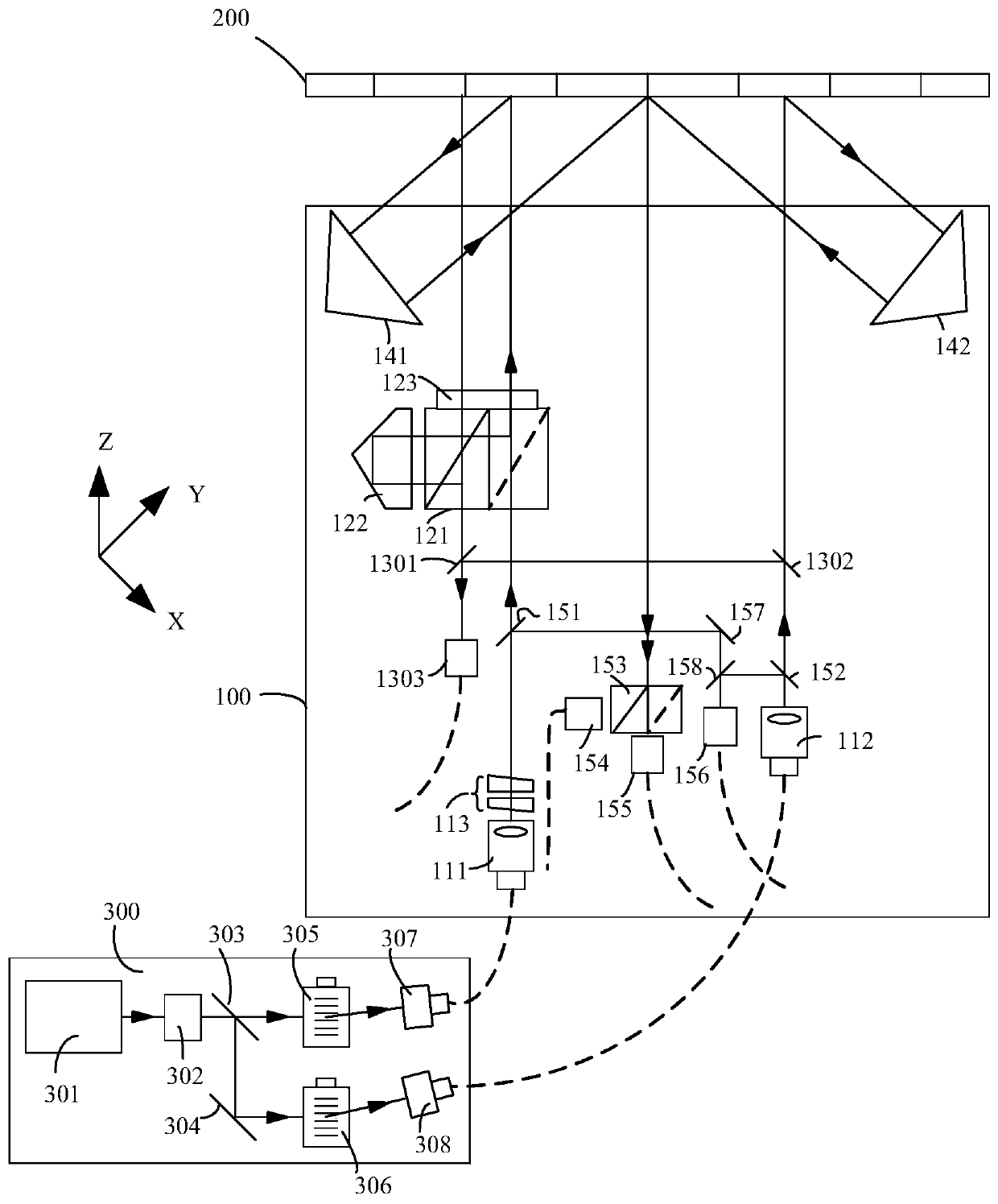
[0101] The difference between this embodiment and Embodiment 1 is that this embodiment can realize vertical and horizontal displacement measurement at the same time.

[0102] Such as image 3 As shown, compared with Embodiment 1, this embodiment adds: a vertical measurement module arranged on the optical path between the dual-frequency incident light module and the grating 200, and a vertical detection module corresponding to the vertical measurement module .

[0103] Continue to refer to image 3 , the vertical measurement module includes: a second polarization beam splitter prism 121, a second corner cube prism 122, and a polarization controller 123. The measurement beam emitted by the dual-frequency incident light module is first transmitted through the second polarization beam splitter prism 121, and is controlled by polarization. The polarizer 123 rotates the polarization direction and projects onto the grating 200 to diffract. The -1 order diffracted light in the diffr...

Embodiment 3

[0111]The difference between this embodiment and Embodiment 2 is that the vertical detection module in this embodiment does not include the fourth beam splitter 1301, and the measurement beam with vertical displacement information returned by the grating is combined with the fifth beam splitter in other ways. The reference beams split by the beam mirror 1302 are combined to form an interference signal a1 to realize vertical measurement. Such as Figure 5 As shown (the part used for horizontal measurement is not shown in the figure), the reference beam is reflected by the fifth beam splitter 1302, enters the second polarization beam splitter 121, and is merged with the measuring beam with the vertical position signal and then is The fourth remote coupler 1303 couples the output.

[0112] The scheme for combining light beams shown in this device can be implemented in a variety of ways. It can be implemented in embodiment 2 through the fourth beam splitter 1301 to combine light ...


PUM


Abstract

The invention discloses an optical grating measurement device. The optical grating measurement device includes a light source module, an optical grating, a signal processing module and an optical grating measurement probe, wherein the light source module is used for generating two light beams with different frequencies, and the optical grating measurement probe includes a dual-frequency light incoming module, a horizontal direction detection module, a reference detection module and two symmetrically-arranged retroreflectors; the dual-frequency light incoming module is used for receiving the two light beams and projecting the same onto the surface of the optical grating and the reference detection module; the two light beams are projected onto the reference detection module and are subjected to interference so as to form reference interference signals; the two light beams are diffracted on the surface of the optical grating, and diffracted light is respectively projected onto the corresponding retroreflectors; the retroreflectors retroreflect the light onto the surface of the optical grating; the light is subjected to secondary diffraction; the light which has been subjected to secondary diffraction is converged and projected onto the horizontal direction detection module and is subjected to interference so as to form horizontal direction displacement interference signals; and the signal processing module detects the horizontal direction displacement interference signals and the reference interference signals and calculates the horizontal displacement of the optical grating.With the optical grating measurement device of the invention adopted, horizontal plane X-Y-direction two-dimensional simultaneous detection for the same measurement point can be realized.

Description

technical field [0001] The invention relates to the field of integrated circuit manufacturing, in particular to a grating measuring device. Background technique [0002] Nano-measurement technology is the foundation of nano-processing, nano-manipulation, nano-materials and other fields. The IC industry, precision machinery, micro-electromechanical systems, etc. all require high-resolution, high-precision displacement sensors to achieve nanometer-precision positioning. With the rapid development of integrated circuits in the direction of large-scale and high integration, the requirements for overlay accuracy of lithography machines are getting higher and higher. Correspondingly, the accuracy of obtaining six-degree-of-freedom position information of workpiece tables and mask tables also increased. [0003] The interferometer has a high measurement accuracy, which can reach the nanometer level. In the lithography system, it is used to measure the position of the workpiece st...

Claims


Application Information

Patent Timeline
Patent Type & Authority Patents(China)
IPC IPC(8): G01B11/02
CPCG01B11/02
Inventor 吴萍张志平
Owner SHANGHAI MICRO ELECTRONICS EQUIP (GRP) CO LTD
Learn More