Marine gas hydrate and mortar replacement exploitation method and device
A mining method and hydrate technology, which is applied in the direction of mining fluid, earthwork drilling, wellbore/well components, etc., can solve the problems of decreased seepage capacity of the near-wellbore formation, unfavorable formation stability, and aggravated large-area deficit of the wellbore, so as to maintain Formation stability, the effect of preventing large-area deficits in the formation
- Summary
- Abstract
- Description
- Claims
- Application Information
AI Technical Summary
Problems solved by technology
Method used
Image
Examples
Embodiment 1
[0037] Embodiment 1. This embodiment discloses a mortar replacement mining method for marine natural gas hydrate, which includes the following steps: (1) Open the overlying strata of the hydrate reservoir, use the production casing to lower the strata above the hydrate reservoir and perform solidification. Well operation; (2) Open the hydrate reservoir and open hole gravel packing, install and lower the wellbore string combination; (3) Use the depressurization method or formation fluid extraction method to start hydrate production, and at the same time inject liquid into the wellbore, Sand-carrying production; while step (3) is being carried out, large-size mortar is filled into the formation to continue production, and during the implementation of step (3), real-time adjustment of liquid injection parameters and mortar injection parameters to maintain production.
[0038] According to conventional procedures, a hydrate production well is opened with a large borehole drill bit,...
Embodiment 2
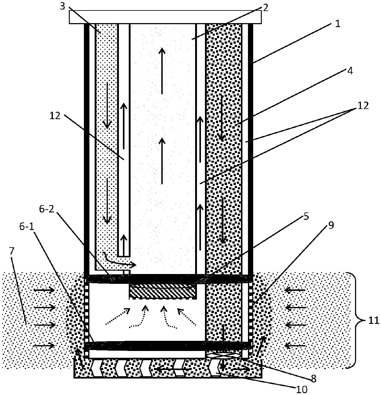
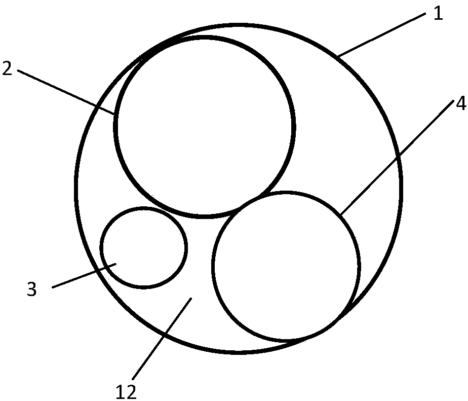
[0050] Example 2. Based on the mining method proposed in Example 1, this example proposes a marine natural gas hydrate mortar displacement mining device, which is designed according to the principle of "1+3", that is, one large-diameter casing + three small Diameter casing (or tubing), ref. figure 2 , including production casing 1, production tubing 2 arranged in production casing 1 and parallel to the axis of production casing, wellbore water injection pipe 3 and mortar reinjection pipe 4; production tubing 2, wellbore water injection pipe 3 and mortar reinjection pipe The annular space formed between the outer wall of the production casing 1 and the inner wall of the production casing 1 is the gas circulation channel 12 .
[0051] Specifically, such as figure 1 As shown in the schematic diagram of the principle structure, the lower end of the production casing 1 is connected with a matching mechanical screen 9, and the production casing 1 is located above the production la...
PUM
 Abstract
Description
Claims
Application Information
 - R&D
- Intellectual Property
- Life Sciences
- Materials
- Tech Scout
- Unparalleled Data Quality
- Higher Quality Content
- 60% Fewer Hallucinations
Browse by: Latest US Patents, China's latest patents, Technical Efficacy Thesaurus, Application Domain, Technology Topic, Popular Technical Reports.
© 2025 PatSnap. All rights reserved.Legal|Privacy policy|Modern Slavery Act Transparency Statement|Sitemap|About US| Contact US: help@patsnap.com


