Integrated test stand for unmanned aerial vehicle induction motor and test method
An induction motor, comprehensive testing technology, applied in the direction of motor generator testing, etc., can solve the problem of unmanned aerial vehicle motor measurement, and achieve the effect of avoiding measurement and calculation errors, saving time and energy, and high accuracy.
- Summary
- Abstract
- Description
- Claims
- Application Information
AI Technical Summary
Problems solved by technology
Method used
Image
Examples
Embodiment 1
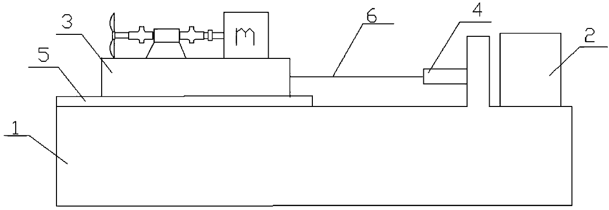
[0034] Such as figure 1 As shown, the UAV induction motor comprehensive test bench includes the experimental bench 1, the upper computer 2 and the motor test group; each motor test group has a motor mount 3 for installing the motor to be tested. The motor to be tested is connected with a speed sensor and a torque sensor. It also includes a tension sensor 4 and a slide rail 5. The motor mount 3 is connected to the upper end surface of the test bench 1 through the slide rail 5. One end of the motor mount 3 is connected to a separate metal rope 6, and each metal rope 6 is connected to a separate tension sensor 4. One end is connected, the other end of the tension sensor 4 is fixed on the test bench 1 , and the tension sensor 4 is electrically connected with the host computer 2 . It also includes a UAV propeller, which is connected with a torque sensor through a coupling.
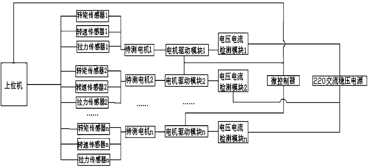
[0035] Such as figure 2 As shown, the motor to be tested in each motor test group is connected to a spee...
Embodiment 2
[0043] In this embodiment, a drone with 4 propellers is only installed on the upper end of the drone body. The user first inputs n=4 on the host computer 2, and the current air density is 1.185kg / m 3 , according to the angle of attack of the propeller, the pull coefficient obtained from the table is 0.6, and the area of the propeller is 40cm 2 , the length of the blade is 12cm, the mass of the drone is 240g, and the flight mode is hovering. The host computer can calculate the theoretical rotational angular velocity of each propeller. Theoretically, the lifting force generated by the four propellers at this time is the weight of the drone. According to this value, the speed of the propellers can be obtained as 120r / min.
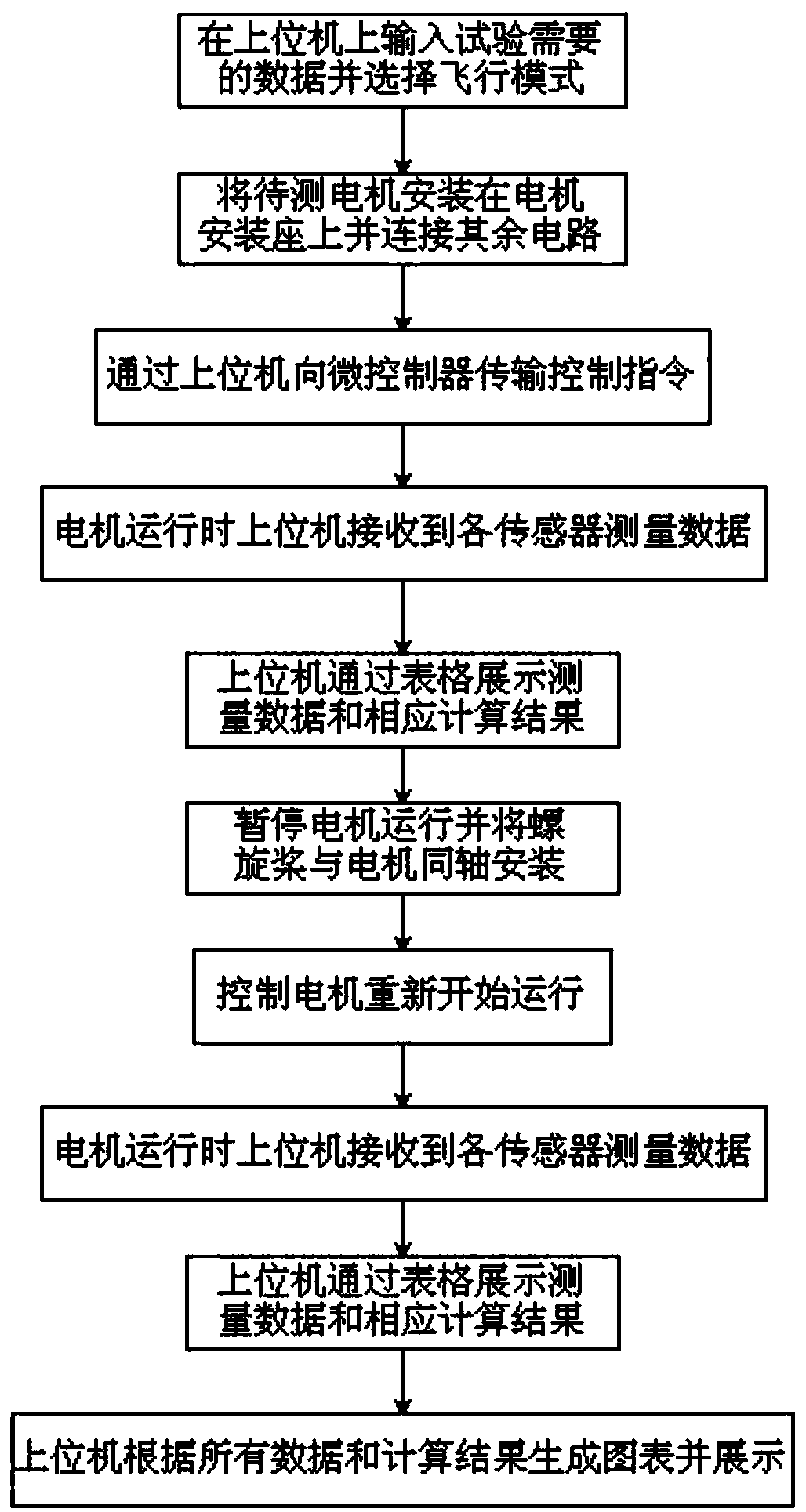
[0044] When testing the motor, the microcontroller controls the motor to run, and detects the speed, torque and voltage and current of each motor. The upper computer calculates the input power, output power and efficiency of the motor. Then attach the pr...
Embodiment 3
[0046] In this embodiment, a drone with 8 propellers is tested only on the upper end of the drone body. The user first inputs n=8 on the host computer 2, and the current air density is 1.185kg / m 3 , according to the angle of attack of the propeller, the pull coefficient obtained from the table is 0.6, and the area of the propeller is 40cm 2 , the length of the blade is 12cm, the mass of the drone is 240g, and the flight mode is hovering. The host computer can calculate the theoretical rotational angular velocity of each propeller. Theoretically, the lifting force generated by the 8 propellers at this time is the weight of the drone. According to this value, the speed of the propellers can be obtained as 85r / min.
[0047] When testing the motor, the microcontroller controls the motor to run, and detects the speed, torque and voltage and current of each motor. The upper computer calculates the input power, output power and efficiency of the motor. Then attach the propeller...
PUM
 Abstract
Description
Claims
Application Information
 - R&D
- Intellectual Property
- Life Sciences
- Materials
- Tech Scout
- Unparalleled Data Quality
- Higher Quality Content
- 60% Fewer Hallucinations
Browse by: Latest US Patents, China's latest patents, Technical Efficacy Thesaurus, Application Domain, Technology Topic, Popular Technical Reports.
© 2025 PatSnap. All rights reserved.Legal|Privacy policy|Modern Slavery Act Transparency Statement|Sitemap|About US| Contact US: help@patsnap.com


