
Cylindrical power battery module

A technology for power batteries and cylindrical batteries, which is applied to battery pack components, circuits, electrical components, etc., can solve problems such as potential safety hazards, low modularization, and low space utilization, and achieve improved vibration resistance and impact resistance. The effect of strong versatility and convenient operation

Pending Publication Date: 2018-02-09
BEIJING PRIDE NEW ENERGY BATTERY
View PDF11 Cites 6 Cited by
  • Summary
  • Abstract
  • Description
  • Claims
  • Application Information

AI Technical Summary

Problems solved by technology

[0003] At present, most of the group manufacturing of cylindrical battery modules in the industry uses screws to string multiple cylindrical battery modules together and fix the ends with nuts. Since the modules will be subject to vibration and impact during use, the nuts are easy to loosen; the bolt heads and nuts There are many protruding end plates, resulting in low utilization of module space; there is a clearance fit between the screw and the module sleeve, and the module will move in series in the vertical direction in practical applications
Moreover, the positive and negative pole protective covers of traditional cylindrical battery modules have a single outgoing direction, and the modules will be placed in different directions in practical applications. The single outgoing direction will easily lead to difficulties in high-voltage connections.
There are various problems such as low modularization, low space utilization, cluttered electrical lines, and uneven heat conduction of batteries, which greatly reduce the production efficiency and product quality of battery modules and battery systems, and shorten the service life of battery systems. There are also major security risks

Method used


Image

  • Cylindrical power battery module
  • Cylindrical power battery module
  • Cylindrical power battery module

Examples


Embodiment Construction

[0024] Various embodiments of the invention will be described in more detail below with reference to the accompanying drawings. In the various drawings, the same elements are denoted by the same or similar reference numerals.

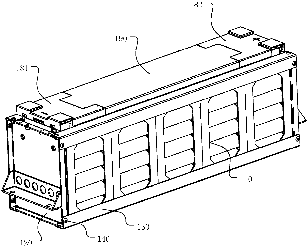
[0025] figure 1 A schematic diagram showing a three-dimensional structure of a cylindrical power battery module according to an embodiment of the present invention.

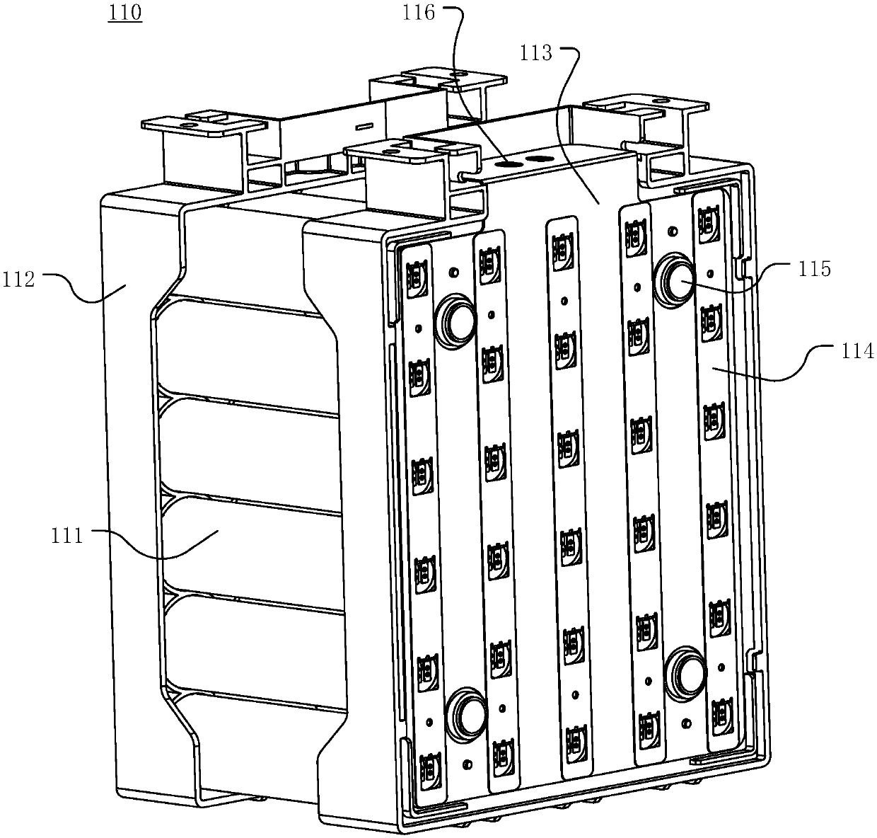
[0026] The cylindrical power battery module in the embodiment of the present invention includes: a battery module 110 , an end plate 120 , an angle steel 130 , a rivet 140 , a negative upper cover 181 , a positive upper cover 182 and a middle upper cover 190 .

[0027] figure 1 Shown is a schematic diagram of the assembly of the cylindrical power battery module. The battery module includes a plurality of battery modules 110 connected in series, which are fixed by a module frame composed of angle steel 130 and end plates 120 on both sides. Rivet holes are provided on the end plates 120 ,...


PUM


Abstract

The invention discloses a cylindrical power battery module. The cylindrical power battery module comprises a plurality of battery modules, a plurality of electric connecting sheets positioned among adjacent battery modules and used for connecting the multiple battery modules, a module frame used for accommodating and fixing the multiple battery modules, and a battery upper cover used for coveringand protecting the multiple battery modules, wherein the module frame comprises two end plates and four fixed steel angles; the fixed steel angles and the end plates are connected in a riveting manner; and the battery upper cover comprises a positive polar column upper cover, a negative polar column upper cover and a middle upper cover. The cylindrical power battery module provided by the invention adopts the multiple battery modules which can be freely assembled, so that a high-voltage and high-capacity battery system can be formed through series-parallel connection according to needs; the cylindrical power battery module is simple in structure, convenient to assemble and high in universality and interchangeability; and by virtue of the riveting mode, the overall impact resistance and vibration resistance of the module can be improved.

Description

technical field [0001] The invention relates to the field of power batteries, in particular to a riveted cylindrical power battery module. Background technique [0002] At present, the global automobile industry is facing the huge challenge of energy and environmental issues; pure electric vehicles with high energy utilization rate and no pollution to the environment are increasingly becoming the development direction of the future automobile industry. As the core component of a pure electric vehicle, the performance of a power battery will directly affect the performance of a pure electric vehicle. The energy provided by a single battery is limited. To meet the electric energy demand of the electric vehicle power battery system or the national grid energy storage battery system, multiple lithium-ion batteries need to be connected in series and parallel to form a power battery module. The battery module will be subject to certain vibration and impact during the driving proc...

Claims


Application Information

Patent Timeline
Patent Type & Authority Applications(China)
IPC IPC(8): H01M2/20H01M2/10H01M50/242H01M50/258H01M50/264H01M50/51H01M50/517
CPCH01M50/502H01M50/20Y02E60/10
Inventor 袁格年赵孟黄伟盛力
Owner BEIJING PRIDE NEW ENERGY BATTERY
Learn More