Vertical pyrolysis furnace

A pyrolysis furnace, vertical technology, used in coke ovens, direct heating and dry distillation, petroleum industry and other directions, can solve the problems of affecting production progress, restricting continuous production of devices, and small number of jet pipes, etc., to achieve the effect of improving production efficiency

Pending Publication Date: 2018-02-13
SHENWU TECH GRP CO LTD
View PDF0 Cites 5 Cited by
  • Summary
  • Abstract
  • Description
  • Claims
  • Application Information

AI Technical Summary

Problems solved by technology

However, the pyrolysis furnace does not mention the problem of feeding and semi-coke discharge, and the semi-coke needs to be cooled before it can be discharged, which restricts the continuous production of the device. At the same time, the small number of gas injection pipes in the pyrolysis furnace restricts The pyrolysis gas is evenly distributed, and the hemispherical damping device needs to be replaced and repaired regularly, which affects the production progress

Method used


Image

  • Vertical pyrolysis furnace
  • Vertical pyrolysis furnace

Examples


example 1

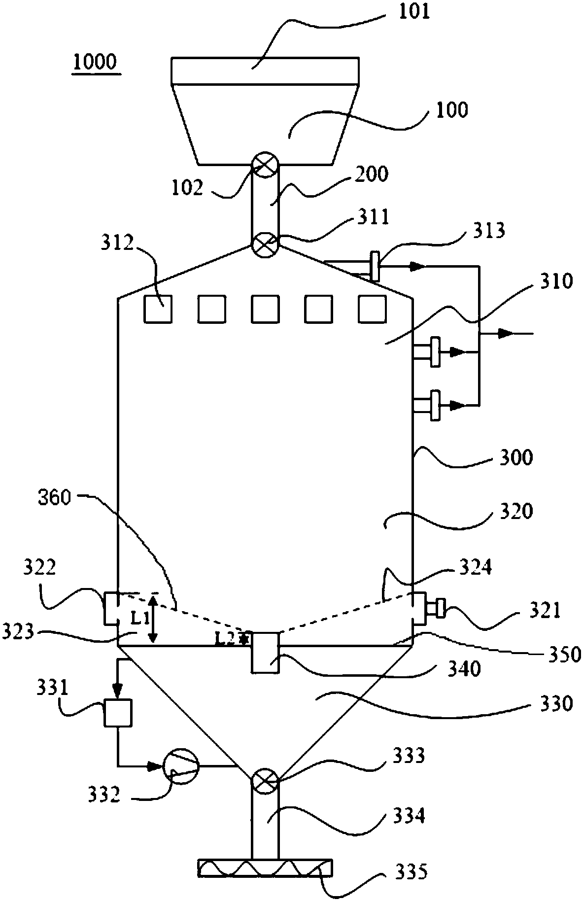
[0069] This example 1 uses figure 1 with figure 2 The vertical pyrolysis furnace 1000 shown as an example is as follows:

[0070] Using hot converter gas as the heat carrier gas to pyrolyze low-rank coal, specifically: converter gas flow rate is 25000Nm 3 / h, the temperature before entering the furnace is 1050℃, which contains about 65% of CO, CO 2 About 20%, N 2 About 15%. The converter gas is introduced from the heat-carrying gas inlet 321 at the bottom of the vertical pyrolysis furnace 1000, and the low-rank coal pellets or particles from the bottom up and down fully exchange heat, and the low-rank coal pellets or particles are heated to 950°C to promote low The rank coal undergoes a pyrolysis reaction, and the converter gas is mixed with the generated pyrolysis gas, and is discharged from the middle and upper part of the vertical pyrolysis furnace 1000 through the pyrolysis gas outlet 313. Among them, the particle size of low-rank coal pellets is 6-16mm, the pyrolysis capaci...

example 2

[0072] This example 1 uses figure 1 with figure 2 The shown vertical pyrolysis furnace 1000 is taken as an example, and the details are as follows:

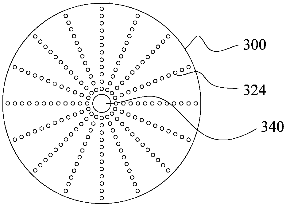
[0073] The temperature of the hot carrier gas before entering the furnace is 950℃, and the flow rate of the hot carrier gas is 30000Nm 3 / h, which contains about 75% of CO, CO 2 About 15%, N 2 About 10%. The heat-carrying gas is introduced from the nozzle 324 at the bottom of the vertical pyrolysis furnace 1000, and the lower-rank coal pellets or particles are fully heat exchanged from bottom to upper and descending, and the lower-rank coal pellets or particles are heated to 900°C to promote the lower-rank coal The pyrolysis reaction occurs, and the converter gas is mixed with the generated pyrolysis gas, and is discharged from the middle and upper part of the vertical pyrolysis furnace 1000 through the pyrolysis gas outlet 313. Among them, the particle size of low-rank coal pellets is 6-12mm, the pyrolysis capacity of low-rank coa...


PUM


Abstract

The invention discloses a vertical pyrolysis furnace. The vertical pyrolysis furnace includes a furnace body, and the furnace body defines a preheating section, a pyrolysis section and a cooling section from top to bottom. The preheating section and The pyrolysis section is connected, a partition is provided between the pyrolysis section and the cooling section, and the bottom of the pyrolysis section is provided with a wall that passes through the partition and extends into the cooling section. A discharge pipe, the furnace body is provided with a pyrolysis material inlet connected to the preheating section, a heat carrier gas inlet connected to the pyrolysis section, a heat carrier connected to the preheating section and/or the pyrolysis section Degassing outlet, the bottom of the furnace body is provided with a semi-coke outlet that communicates with the cooling section. According to the vertical pyrolysis furnace of the embodiment of the present invention, the continuous operation of the pyrolysis furnace can be realized by setting the connected preheating section, pyrolysis section and cooling section, and the production efficiency is improved.

Description

Technical field [0001] The invention relates to the technical field of coal gasification and pyrolysis equipment, in particular to a vertical pyrolysis furnace. Background technique [0002] Coal pyrolysis means that the coal is heated to a higher temperature under the condition of isolating the air. As the temperature increases, the organic matter in the coal undergoes a series of physical and chemical changes, and finally decomposes into solid semi-coke, pyrolysis gas and other substances The reaction process. Among them, the coal pyrolysis furnace is the core equipment of the coal pyrolysis process. At present, the main types of pyrolysis equipment at home and abroad are divided into three categories: fluidized bed, fixed bed and rotary kiln. The fluidized bed has higher requirements for materials, more complicated control operations, and smaller scope of application. The control system of the fixed bed equipment is relatively simple to operate, but the materials are heated...

Claims


Application Information

Patent Timeline
Patent Type & Authority Applications(China)
IPC IPC(8): C10B49/02
CPCC10B49/02
Inventor 冯鲁兴邓君唐敬坤韩志彪曹志成汪勤亚吴道洪
Owner SHENWU TECH GRP CO LTD
Why Eureka
Try Eureka