
TDLAS boiler gas two-dimensional concentration distribution detecting method and device based on automatic scanning system

An automatic scanning and concentration distribution technology, which is applied in the analysis of materials, color/spectral characteristic measurement, instruments, etc., can solve the problems affecting the reconstruction quality of the concentration distribution image, insufficient effective projection data, and difficulty in popularization and application, and achieves a reduction in the number of lasers, The effect of improving reconstruction accuracy and reducing overall cost

Pending Publication Date: 2018-02-13
NORTH CHINA ELECTRIC POWER UNIV (BAODING)
View PDF0 Cites 9 Cited by
  • Summary
  • Abstract
  • Description
  • Claims
  • Application Information

AI Technical Summary

Problems solved by technology

[0003] Theory and practice have proved that it is feasible to apply TDLAS technology combined with tomography technology to the two-dimensional distribution detection of gas component concentration field in power plant boilers, and a large number of simulation results and experimental data have verified that the more light paths passing through the area to be measured, The better the reconstruction quality of the concentration distribution image is, but the lasers and detectors in the existing TDLAS gas detection system mostly adopt a fixed arrangement, which limits the number of optical paths, resulting in insufficient effective projection data, which seriously affects the quality of the concentration distribution image reconstruction, and is difficult to popularize. application

Method used


Image

  • TDLAS boiler gas two-dimensional concentration distribution detecting method and device based on automatic scanning system
  • TDLAS boiler gas two-dimensional concentration distribution detecting method and device based on automatic scanning system
  • TDLAS boiler gas two-dimensional concentration distribution detecting method and device based on automatic scanning system

Examples


Embodiment Construction

[0031] The present invention will be described below according to the embodiments shown in the accompanying drawings. It can be thought that embodiment disclosed this time is an illustration in every point, and is not restrictive. The scope of the present invention is not limited by the description of the following embodiments but only by the scope of the claims, and includes the same meaning as the scope of the claims and all modifications within the scope of the claims.

[0032] The structure of the present invention will be described below in conjunction with specific embodiments.

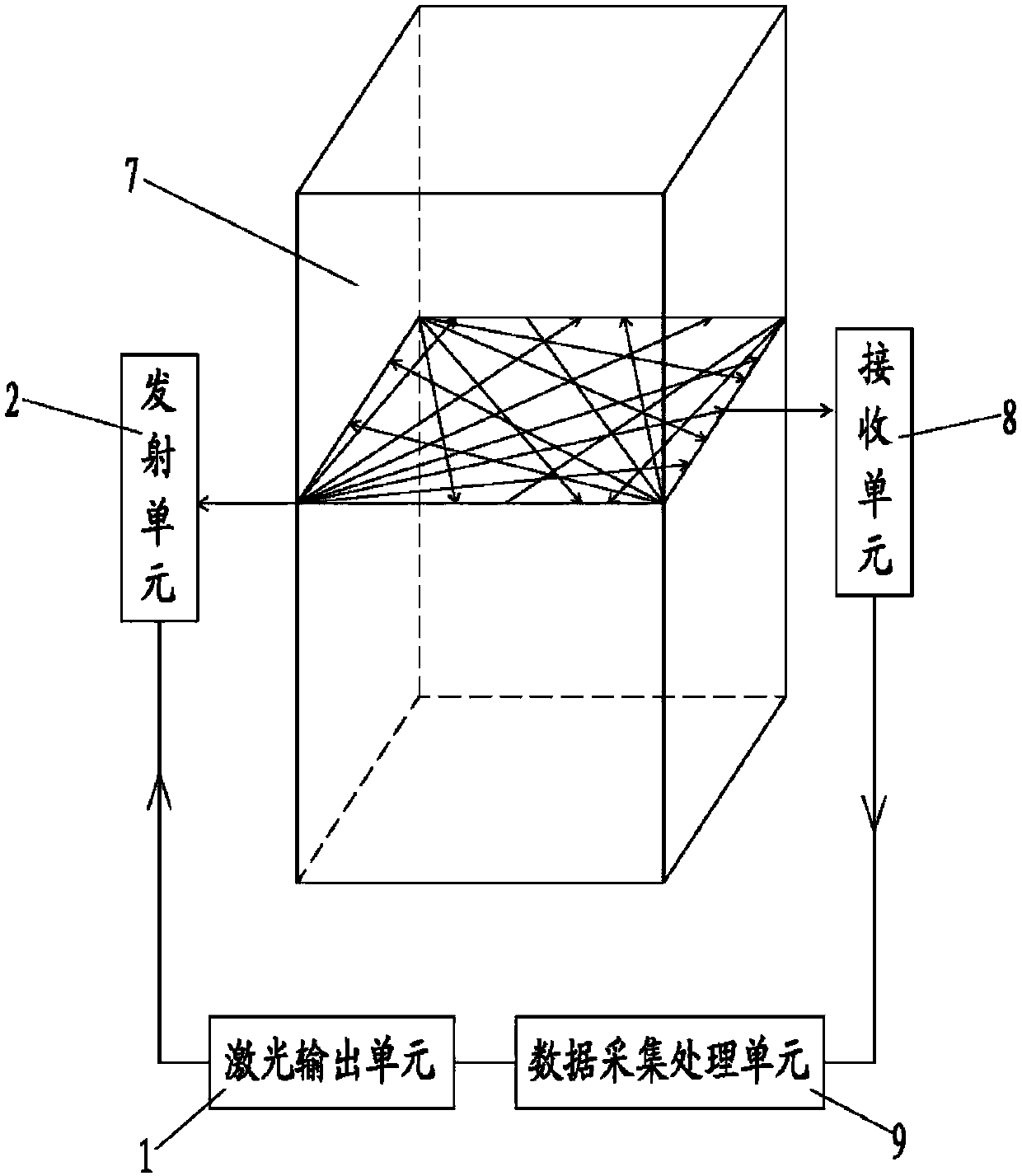
[0033] like figure 1 Shown is the structural schematic diagram of Embodiment 1 of the TDLAS boiler furnace gas two-dimensional concentration distribution detection device based on the automatic scanning system of the present invention, including:

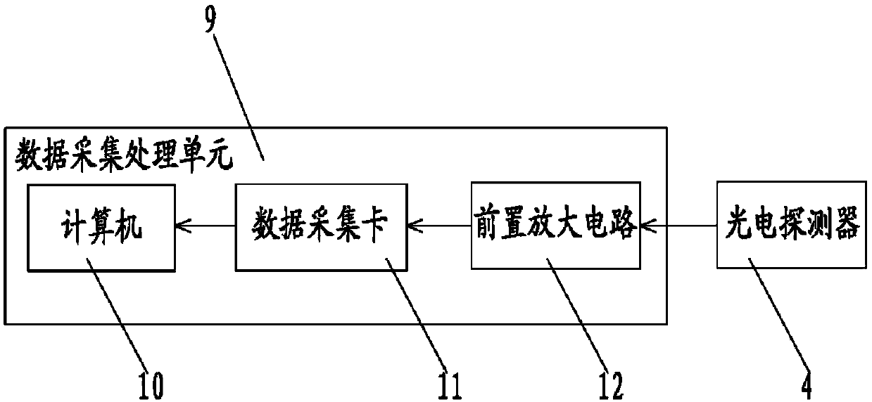
[0034] Laser output unit 1: used to output a beam of laser light to each emission unit 2, combined with figure 2 As shown, the laser output unit ...


PUM


Abstract

The invention discloses a TDLAS boiler gas two-dimensional concentration distribution detecting method based on an automatic scanning system. The method includes that a transmitting unit is mounted ateach of four corners of a boiler hearth section detection platform; multiple receiving units are mounted on four sides of the detection platform; the transmitting units and the receiving units are enabled to rotate according to a preset mode through a control module, and when a laser beam rotates to scan a hearth inside section, the laser beam directly faces the receiving units scanned by the laser beam when rotating sequentially to enable the receiving units to sequentially complete receiving of laser transmission signals and convert the same into electric signals; collected analog signals are converted into digital signals and output to a computer through a data collection card, and to-be-detected gas two-dimensional concentration distribution of a scanned area is calculated inversely through an image reconstruction algorithm. A detecting device comprises a laser output unit, a transceiving unit and a data collecting and processing unit. By the method, boiler hearth inside section gas product concentration distribution can be detected accurately in real time, gas concentration two-dimensional distribution reconstruction quality is improved effectively, and detection cost is lowered.

Description

technical field [0001] The invention relates to the technical field of gas concentration detection, in particular to a method and device for detecting gas two-dimensional concentration distribution in a boiler furnace using TDLAS based on an automatic scanning system. Background technique [0002] The on-line measurement of product concentration and distribution of combustion gas in controllable combustion spaces such as power plant boilers is of great significance for realizing combustion optimization, improving combustion efficiency and flame quality, and reducing pollutant emissions. Tunable Laser Absorption Spectroscopy (TDLAS) is an emerging spectroscopic measurement technology for gas components. With its high spectral resolution, high accuracy, fast response speed, high sensitivity and low interference from other gases, it has become an Effective monitoring means for gas, industrial air leakage, high-temperature and high-speed exhaust gas, etc. [0003] Theory and pr...

Claims


Application Information

Patent Timeline
IPC IPC(8): G01N21/39
CPCG01N21/39G01N2201/117
Inventor 黄孝彬陈雪雨
Owner NORTH CHINA ELECTRIC POWER UNIV (BAODING)
Learn More