Device for supplying power from aerial power generation robot to high-rise lighthouse

A power supply device and robot technology, applied in battery circuit devices, water supply devices, circuit devices, etc., can solve problems such as the difficulty of supplementing power for navigation lights, and achieve the effects of air pollution control and high work efficiency

Inactive Publication Date: 2018-02-13
WUXI TONGCHUN NEW ENERGY TECH
View PDF0 Cites 1 Cited by
  • Summary
  • Abstract
  • Description
  • Claims
  • Application Information

AI Technical Summary

Problems solved by technology

[0003] In the sea with high waves and rough water, it is necessary to build high-rise lighthouses to emit bright lights at night to prevent ships from colliding with dangerous reefs and dark rocks and traffic accidents. However, it is very difficult to supplement the power of the navigation lights of such high-rise lighthouses.

Method used


Image

  • Device for supplying power from aerial power generation robot to high-rise lighthouse

Examples


Embodiment 1

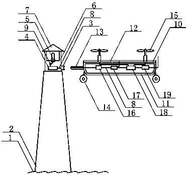
[0023]After the energy storage battery B of the aerial power generation robot is fully stored in the sky with clean energy photovoltaic power from photovoltaic power generation, it will fly to the high-rise lighthouse completely relying on solar power, and supply power to the navigation lights and other electrical appliances on the top of the high-rise lighthouse through the receiving charging device. Sunlight irradiates the monocrystalline silicon thin-film solar cells installed on the top surface of the carbon fiber frame of the aerial power generation robot, and the current generated is input into the energy storage battery B through conductive wires and photovoltaic controllers for storage, and no carbon dioxide or sulfur dioxide is emitted during the photovoltaic power generation process in the air and other polluting gases. A small part of the current output from the energy storage battery B is respectively input into 6 flight elevators installed equidistantly through con...

Embodiment 2

[0025] After the energy storage battery B of the aerial power generation robot is fully stored in the sky with clean energy photovoltaic power from photovoltaic power generation, it will fly to the high-rise lighthouse completely relying on solar power, and supply power to the navigation lights and other electrical appliances on the top of the high-rise lighthouse through the receiving charging device. The sunlight irradiates the polysilicon thin-film solar cells installed on the top surface of the carbon fiber frame of the aerial power generation robot, and the current generated is input into the energy storage battery B through conductive wires and photovoltaic controllers for storage. In the process of photovoltaic power generation in the air, no pollution such as carbon dioxide and sulfur dioxide is emitted. gas. A small part of the current output from the energy storage battery B is respectively input into 8 flight elevators installed equidistantly through conductive wires...


PUM


Abstract

The invention relates to a device for supplying power from aerial power generation robot to a high-rise lighthouse and belongs to the technical field of clean energy application. Current generated bythin-film solar cells irradiated by sunlight and mounted on the top surface of a carbon fiber frame of the aerial power generation robot is input into a second energy storage battery for storage through an electric lead and a photovoltaic controller, so that no pollution gas is emitted into the air in the process of photovoltaic power generation. A small part of the current output from the secondenergy storage battery powers a flying elevator and a wireless communication device while most of the current powers a receiving charging device on the high-rise lighthouse through a charging controller and an intelligent charging gun, and the current received by the receiving charging device is input into a first energy storage battery for storage through an electric lead. At night, a photosensitive self-control switch automatically turns on a circuit, and the current output from the first energy storage battery powers a beacon light through an electric lead and the photosensitive self-control switch to lighten navigation paths of night navigation ships. What the aerial power generation robot supplies to the high-rise lighthouse is 100% clean energy-photovoltaic power.

Description

technical field [0001] The invention relates to a power supply device for an aerial power generation robot to a high-rise lighthouse, and belongs to the technical field of clean energy application. Background technique [0002] In the past two hundred years, human society has used a large amount of fossil energy in the process of industrialization, burned a large amount of coal and oil, and emitted 1,692.6 billion tons of carbon dioxide into the air on the earth, as well as a large amount of sulfur dioxide, nitrogen oxides, etc. Harmful gases have caused air pollution, smog appeared in the air near the ground, and brown clouds of pollutants accumulated in the upper air appeared. The residence time of carbon dioxide in the air is more than 200 years. Controlling air pollution will be a long term work. Due to air pollution, human diseases have increased and life expectancy shortened in some areas. In terms of ecological environment, climate change, temperature rise, seawater...

Claims


Application Information

Patent Timeline
Patent Type & Authority Applications(China)
IPC IPC(8): H02J7/35H02J7/00F21V23/04F21W111/043
CPCF21V23/0464F21W2111/043H02J7/342H02J7/35
Inventor 林华
Owner WUXI TONGCHUN NEW ENERGY TECH
Why Eureka
Try Eureka