Micro fluidic chip device for multichannel simultaneous detection of six typical tumor markers

A technology of microfluidic chips and tumor markers, applied in the field of microfluidic chip devices, can solve problems that have not been properly solved, large flow resistance, troublesome operation of modifying the inner surface of PDMS microchannels, etc.

Inactive Publication Date: 2018-02-16
宋岳
View PDF4 Cites 1 Cited by
  • Summary
  • Abstract
  • Description
  • Claims
  • Application Information

AI Technical Summary

Problems solved by technology

[0008] But it's not that simple
[0009] First, this polydimethylsiloxane material, the material referred to by the acronym PDMS, is itself a strongly hydrophobic material. Microchannels are built on this material. If the microchannels are not targeted The modification operation of the surface of the channel, then, after the overall assembly is completed, that is, after the cover is covered, because the inner surface of the micro channel in the structure occupies most of the inner surface of the liquid flow channel, then the PDMS micro channel The strong hydrophobic characteristic of the inner surface of the channel is the decisive factor, which will make it very difficult for the polar liquid flow similar to the aqueous solution to pass through, and its flow resistance is so large that even ordinary micropumps are difficult to push. Of course, If the cover sheet also chooses to use the PDMS material, then the problem is basically the same, with little difference; therefore, in the prior art, it is necessary to modify and modify the inner surface of the microchannel on the PDMS material; then , is this modification operation for the inner surface of the PDMS microchannel very troublesome? That's not the problem. What constitutes a serious technical proble...

Method used


Image

  • Micro fluidic chip device for multichannel simultaneous detection of six typical tumor markers

Examples


Embodiment Construction

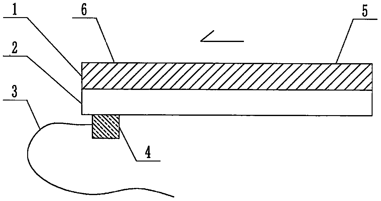
[0056] exist figure 1 In the example shown in this case, the feature of this example is that the structure of the device includes a multi-channel microfluidic chip, and the structure of the microfluidic chip includes a substrate 1 and a cover sheet 2 that are attached to each other. , the substrate 1 and the cover sheet 2 are both plates or sheets, the surface of the substrate 1 facing the cover sheet 2 contains a channel structure formed by a molding process or an etching process, the substrate 1 also includes a window structure connected to the channel structure and pierced through the substrate formed by a molding process, an etching process or a simple drilling process, and the substrate 1 and the cover 2 that are attached to each other are jointly constructed A microfluidic chip containing a pipeline structure and a liquid pool structure connected thereto is formed. The structure of the pipeline is located in the interface area where the substrate 1 and the cover sheet 2 ...


PUM

PropertyMeasurementUnit
Diameteraaaaaaaaaa
Lengthaaaaaaaaaa
Thicknessaaaaaaaaaa

Abstract

The invention relates to a microfluidic chip device for multi-channel simultaneous detection of six typical tumor markers, which belongs to the field of analysis and testing. Using polydimethylsiloxane (PDMS) to make the substrate of the microfluidic chip for multi-channel joint detection of six typical tumor markers has obvious advantages, but there are also a series of problems; this case is aimed at this series of problems. The gist of this case is that the PDMS with an original ecological surface is selected as the substrate, and a micro-ultrasonic transducer is attached and installed in the vicinity of the liquid flow terminal of the microfluidic chip to reduce the interfacial tension with ultrasonic waves, thereby greatly increasing the correlation. The compatibility between the phases and the strong absorption ability of PDMS to ultrasonic waves are used to achieve a rapid decrease in the ultrasonic intensity within a short distance, and thus form a difference in interfacial tension at both ends of the chip, which leads to the difference in interfacial tension between the two A pressure differential is formed at the end of the pipe, which drives the flow toward the terminal along the otherwise strongly hydrophobic pipe.

Description

technical field [0001] The invention relates to a microfluidic chip device for multi-channel simultaneous detection of six typical tumor markers, which belongs to the field of analysis and testing. Background technique [0002] Tumor markers (tumor markers, TM) refer to a class of substances produced by tumor cells themselves or produced by the body's response to tumor cells during the occurrence and proliferation of tumors, reflecting the existence and growth of tumors, including Proteins, hormones, enzymes (isoenzymes) and oncogene products, etc. Testing the tumor markers in the patient's blood or body fluids can detect tumors early in the tumor screening, observe the curative effect of tumor treatment and judge the prognosis of patients. Currently, the tumor markers commonly used clinically are: (1) alpha-fetoprotein (AFP) is a marker for primary liver cancer, testicular cancer, ovarian cancer and other tumors; (2) carcinoembryonic antigen (CEA) is a marker for digestive...

Claims


Application Information

Patent Timeline
IPC IPC(8): B01L3/00G01N33/574G01N27/26
CPCB01L3/502707B01L3/50273B01L3/502746B01L3/502761B01L2200/027B01L2200/10B01L2300/0861B01L2300/12B01L2300/166B01L2400/0439G01N33/57484
Inventor 宋岳
Owner 宋岳
Why Eureka
Try Eureka