
Oil pipeline cleaning device

A technology for oil pipelines and pigging, applied in the direction of cleaning hollow objects, cleaning methods and utensils, chemical instruments and methods, etc., can solve problems such as low efficiency, high pollution, easy jamming, etc., to ensure oil transportation efficiency, reduce loss, the effect of a simple structure

Active Publication Date: 2018-02-16
YANGTZE UNIVERSITY
View PDF5 Cites 3 Cited by
  • Summary
  • Abstract
  • Description
  • Claims
  • Application Information

AI Technical Summary

Problems solved by technology

[0004] The purpose of the present invention is to provide a pigging device for oil pipelines with simple structure and ingenious design to solve the problems of easy jamming, low efficiency, need to stop production, high pollution and other problems existing in the pigging of existing oil pipelines

Method used


Image

  • Oil pipeline cleaning device
  • Oil pipeline cleaning device
  • Oil pipeline cleaning device

Examples


Embodiment Construction

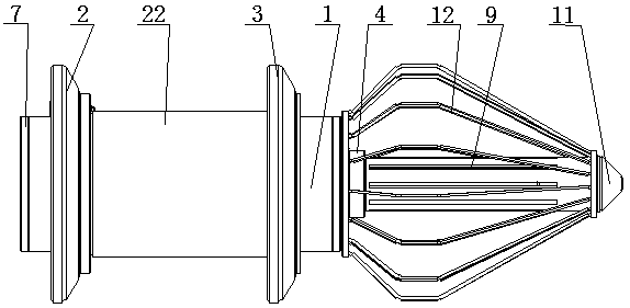
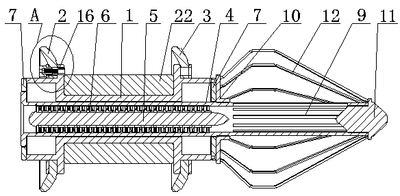
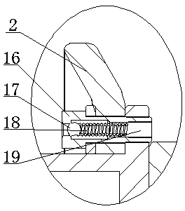
[0030] The oil pipeline pigging device consists of a stator body 1, a scrubber, a front cup 2, a rear cup 3, a rotor body 4, a mandrel 5 and a turbine 6: the stator body 1 is a cylindrical body with an annular space in the middle. The central annular part of the stator body 1 can be used to install the detection locator 22. When the pigging device is in operation, the detection locator 22 will be used to detect the thickness of the oil pipeline and to record the deformation of the pipeline and the position of the thin-walled part; and then It is convenient for people to understand the specific working condition of the pipeline.

[0031] A rotor body 4 is movable inside the stator body 1; the rotor body 4 is a cylinder; one end of the rotor body 4 is provided with an assembly flange 8;

[0032] Both ends of the stator body 1 are fixedly equipped with sealing ring plates 7 , and the sealing ring plates 7 are slidably connected with the rotor body 4 . The purpose of setting the ...


PUM


Abstract

The invention relates to an oil pipeline cleaning device, and belongs to the technical field of oil pipeline dredging equipment. The oil pipeline cleaning device consists of a stator body, a cleaningand brushing device, a front rubber cup, a rear rubber cup, a rotor body, a mandrel and a plurality of turbines; the rotor body is movably arranged in the stator body; one end of the rotor body extends to the outer side of the stator body; the cleaning and brushing device is arranged on the part, extending to the outer side of the stator body, of the rotor body; the turbines are arranged in the part, located in the stator body, of the rotor body through the mandrel; the turbines are fixedly connected with the rotor body; and the front rubber cup and the rear rubber cup are fixedly arranged atthe two ends of the outer side of the stator body correspondingly. The oil pipeline cleaning device is simple in structure and ingenious in design, energy is provided depending on crude oil conveyed in a pipeline without additional motive power, and cleaning on the pipeline is completed by scarping and extrusion drilling; and the oil pipeline cleaning device is especially suitable for oil pipelinecleaning and meets the use requirements of people.

Description

technical field [0001] The invention relates to an oil pipeline pigging device, which belongs to the technical field of oil pipeline dredging equipment. Background technique [0002] In the field of oil production, according to the relevant national regulations and norms, oil pipelines need to be regularly pigged and inspected. By cleaning the pipelines, the transportation efficiency of crude oil and the service life of the pipelines can be improved; the inspection of the pipelines can ensure oil transportation. safety and ensure safe production. [0003] At present, the cleaning methods of oil pipelines mainly include chemical wax removal, washing wax removal, thermal washing wax removal (steam, hot water, hot oil), microbial wax removal, mechanical wax removal, etc. In addition to mechanical wax removal, there are various problems in other wax removal methods, such as production stoppage, high cost, environmental pollution, damaged pipe fittings, high water consumption, w...

Claims


Application Information

Patent Timeline
IPC IPC(8): B08B9/055
CPCB08B9/0557
Inventor 周元华张善彪张慢来
Owner YANGTZE UNIVERSITY
Learn More