Protecting device for large sharpening machine grinding wheel blasting piece

A protection device and grinding machine technology, applied in grinding/polishing safety devices, grinding/polishing equipment, metal processing equipment, etc., can solve problems such as increasing equipment failure, damage to grinding machine equipment, and temperature rise. , to achieve the effect of reducing the probability of failure, weakening the degree of damage, and reducing the flight speed

Active Publication Date: 2018-02-16
SHANXI TAIGANG STAINLESS STEEL CO LTD
View PDF5 Cites 0 Cited by
  • Summary
  • Abstract
  • Description
  • Claims
  • Application Information

AI Technical Summary

Problems solved by technology

[0002] Grinding machine is a device for processing the surface of continuous casting slab. The grinding wheel directly contacts the surface of continuous casting slab, and removes the defects on the surface of continuous casting slab through high-speed rotation; a large amount of heat will be generated during the high-speed cutting of the continuous casting slab surface by the grinding wheel, so that The steel shavings produced by cutting are in a red-hot state, which is very easy to bond with the steel material, and accumulate and grow to form slag, which affects the normal operation of the grinding machine; the red-hot steel shavings bring heat to the bonding part , so that the temperature of the corresponding place rises sharply, which increases the probability of equipment failure; when a grinding wheel burst accident occurs, the grinding wheel fragments fly out along the tangential direction of the grinding wheel, and when they hit the rigid hanger frame, they will rebound and change direction , the grinding wheel fragments flying out at high speed will seriously damage the equipment of the grinding machine, and equipment maintenance must be carried out, which seriously affects production and safety

Method used


Image

  • Protecting device for large sharpening machine grinding wheel blasting piece
  • Protecting device for large sharpening machine grinding wheel blasting piece
  • Protecting device for large sharpening machine grinding wheel blasting piece

Examples


Embodiment

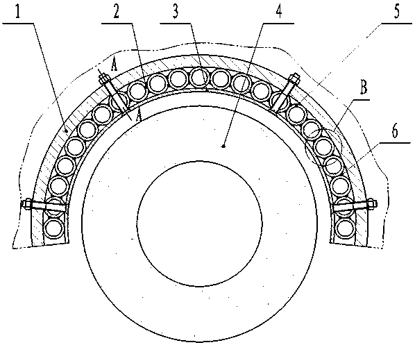
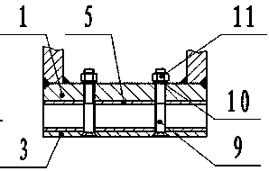
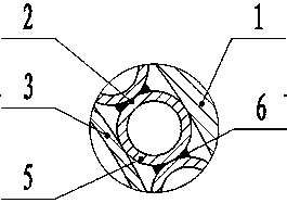
[0018] Such as Figure 1~4 As shown in the figure, a protective device for grinding wheel explosion of a large grinding machine includes a steel pipe group 2, a copper plate 3, and connecting bolts. The inner side of the frame 1 is provided with a steel pipe group 2. The steel pipe group 2 is composed of closely arranged steel pipes 5. The steel pipes 5 are welded to form an arc structure. The inner side of the steel pipe group 2 is provided with a copper plate 3. The frame 1 is fixed by bolts; on the steel pipe group 2, the copper plate 3, and the hanger frame 1, a number of screw holes 7 are evenly arranged along the circumferential direction, and the red copper plate 3, the steel pipe group 2 and the inner wall of the hanger frame 1 are fixed and clamped, Make sure that no relative movement occurs.

[0019] The steel pipe group 2 is attached to the inner wall of the grinder hanger frame 1, and the outer diameter of the arc formed by the steel pipe group 2 is equal to the d...


PUM


Abstract

The invention discloses a protecting device for a large sharpening machine grinding wheel blasting piece. The protecting device is installed on the inner wall of a sharpening machine lifting framework. A steel pipe set is next to the inner wall of the lifting framework. The steel pipe set is formed by steel pipes arranged closely. The steel pipes are welded. A copper plate is next to the inner wall of the steel pipe set. The copper plate and the steel pipe set are fixed to the inner wall of the lifting framework through screws, spring gaskets and nuts. The ends of the bolt holes are provided with 90-degree conical hole structures, so that heads of the installed screws are aligned to the copper plate. According to the method, steel scraps can be prevented from accumulating on the inner surface of the copper plate and forming accumulated slag, a sharpening machine can work normally, heat transmission can be obstructed, temperature of equipment around a grinding wheel is lowered, the probability of failure of a main engine of the sharpening machine is reduced, the damage degree of the grinding wheel blasting piece to the main engine of the sharpening machine is weakened, and the sharpening machine equipment is protected.

Description

technical field [0001] The invention relates to a protective device for a large-scale grinder grinding wheel bursting disc, which belongs to the field of production auxiliary equipment for metallurgical enterprises. Background technique [0002] The grinder is a device for processing the surface of the continuous casting slab. The grinding wheel directly contacts the surface of the continuous casting slab, and removes the defects on the surface of the continuous casting slab through high-speed rotation; a large amount of heat will be generated during the high-speed cutting of the continuous casting slab surface by the grinding wheel. The steel shavings produced by cutting are in a red-hot state, which is very easy to bond with the steel material, and accumulate and grow to form slag, which affects the normal operation of the grinding machine; the red-hot steel shavings bring heat to the bonding part , so that the temperature of the corresponding place rises sharply, which in...

Claims


Application Information

Patent Timeline
Patent Type & Authority Applications(China)
IPC IPC(8): B24B55/04
CPCB24B55/04
Inventor 曹晓东李作健董富生朱美玲孔建勇张勇温斌刘华李炜
Owner SHANXI TAIGANG STAINLESS STEEL CO LTD
Why Eureka
Try Eureka