Transmission mechanism of two-way variable-speed motor

A technology of transmission mechanism and variable speed motor, applied in the field of machinery, can solve the problems of shaking, disengagement and poor working stability of the transmission teeth and the transmission sleeve, and achieve the effect of reliable combination, stable combination and stable operation.

Pending Publication Date: 2018-02-16
屠申富 +1
View PDF2 Cites 4 Cited by
  • Summary
  • Abstract
  • Description
  • Claims
  • Application Information

AI Technical Summary

Problems solved by technology

[0004] However, when the transmission device is performing reverse gear transmission, the connecting sleeve fixed on the transmission teeth and the transmission sleeve are combined to transmit the power of the transmission teeth to the transmission shaft through the connection sleeve and the transmission sleeve sequentially. The transmission sleeves are combined through the tooth-shaped guide part with an arc-shaped inclined surface, and the guide part can also be used to disengage the connecting sleeve and the drive sleeve along the inclined surface, so the inclined surface of the guide part is longer, that is, relatively The bayonet formed between the two adjacent guide parts for snap-in and combination is relatively large. In actual use, the combination is often not in place, and it is easy to shake or even disengage between the transmission gear and the transmission sleeve, and the working stability is poor.

Method used


Image

  • Transmission mechanism of two-way variable-speed motor
  • Transmission mechanism of two-way variable-speed motor
  • Transmission mechanism of two-way variable-speed motor

Examples


Embodiment Construction

[0024] The following are specific embodiments of the present invention and in conjunction with the accompanying drawings, the technical solutions of the present invention are further described, but the present invention is not limited to these embodiments.

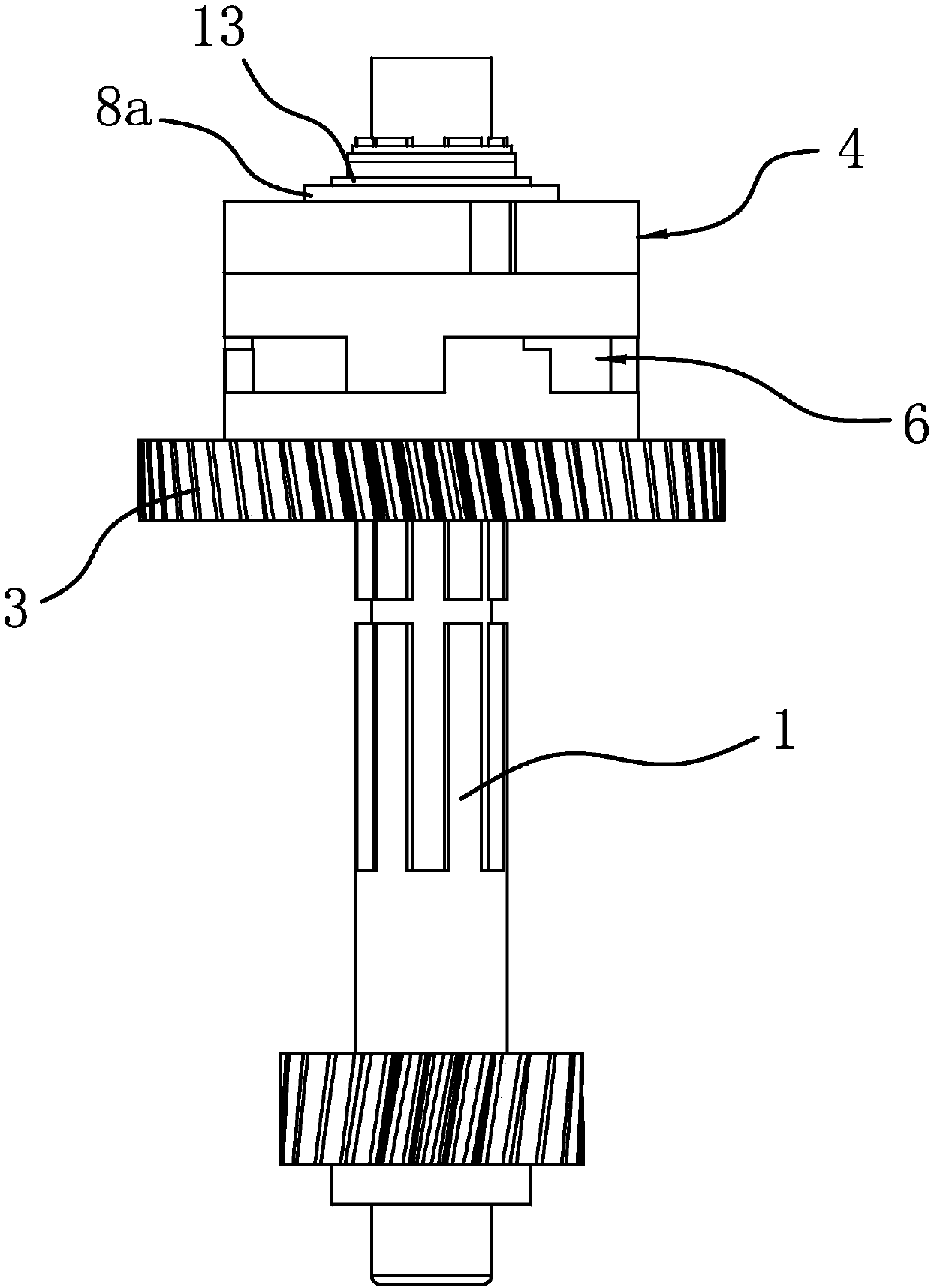
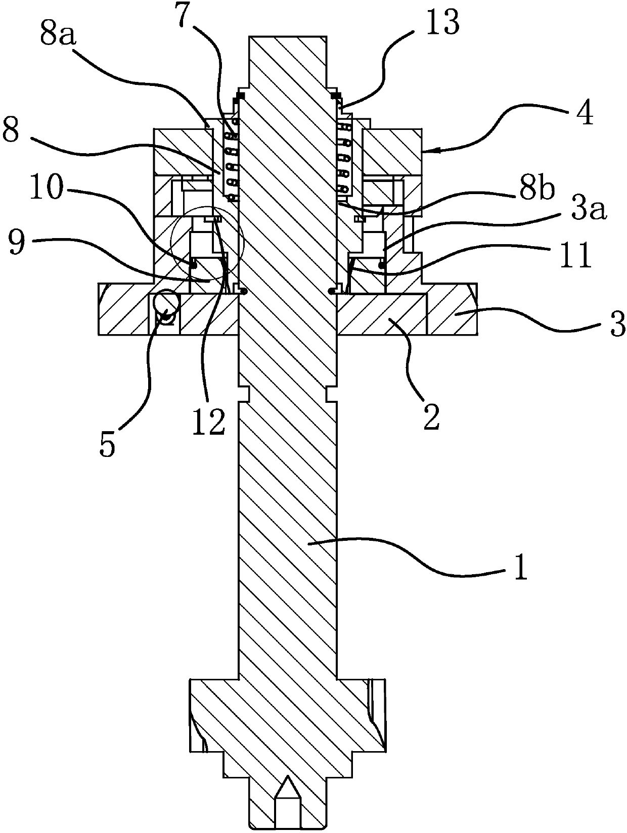
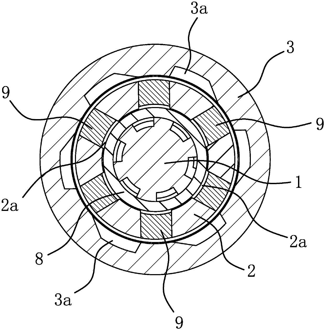
[0025] Such as figure 1 and figure 2As shown, the transmission mechanism of the two-way variable speed motor includes a main shaft 1, an output gear fixedly connected to the main shaft 1, an annular inner ring 2 sleeved outside the main shaft 1 and fixed circumferentially with the main shaft 1, and an inner ring 2. The circular outer ring 3 on the outside and the circular coupling sleeve 4 set on the outer side of the main shaft 1. There is a ring between the inner ring 2 and the outer ring 3 to make the inner ring rotate when the outer ring 3 rotates clockwise. 2 and the slippery one-way structure 5 between the outer ring 3. Between the combination sleeve 4 and the outer ring 3, there is a disengagement structure 6 tha...


PUM


Abstract

The invention provides a transmission mechanism of a two-way variable-speed motor, belongs to the mechanical technical field, and solves the problem that an existing transmission device is poor in working stability. The transmission mechanism of the two-way variable-speed motor comprises a main shaft, an inner ring which sleeves outside the main shaft and is fixed with the main shaft in the peripheral direction, an outer ring which sleeves outside the inner ring and a combined sleeve which sleeves outside the main shaft, wherein a one-way structure is arranged between the inner ring and the outer ring; a separating structure for enabling the combined sleeve to move in a direction away from the outer ring when the outer ring rotates is arranged between the combined sleeve and the outer ring; the transmission mechanism further comprises an elastic part I for enabling the combined sleeve to get close to the outer ring; a combined part and an elastic part II are arranged between the innerring and the outer ring; and when the combined sleeve gets close to the outer ring, the combined part can be driven to move in a mode of overcoming elastic force of the elastic part II; and the innerring and the outer ring are fixedly arranged in the peripheral direction. The transmission mechanism of the two-way variable-speed motor has the advantage of being more stable in work.

Description

technical field [0001] The invention belongs to the technical field of machinery and relates to a transmission mechanism of a bidirectional variable speed motor. Background technique [0002] The transmission mechanism of the two-way variable speed motor is used in the electric tricycle. It realizes the forward or reverse of the electric tricycle through the cooperation of the one-way chuck and other structures. However, the parts of the transmission mechanism of this structure are scattered and occupy too much space. Therefore, the applicant designed a two-way automatic variable speed motor transmission and applied for a Chinese patent (its application number is: CN201520526628.5; its announcement number is: CN204900704U). On the axis of the main shaft, the gap between the various parts is reduced, and the occupied space is reduced. However, the separation mechanism in the transmission device requires extremely high assembly accuracy for each component. If the assembly is ...

Claims


Application Information

Patent Timeline
IPC IPC(8): F16H3/02F16D43/04
CPCF16D43/04F16H3/02
Inventor 屠申富屠昌德
Owner 屠申富
Why Eureka
Try Eureka