Planar electrode structure suitable for vacuum surface flashover

A technology of surface flashover and planar electrode, which is used in the testing of dielectric strength and the construction of testing ships. It can solve problems such as energy band distortion and the impact of flashover results, and achieves reduced electric field distortion, good electric field distribution uniformity, and stable discharge. good effect

Active Publication Date: 2018-02-16
ELECTRIC POWER RESEARCH INSTITUTE OF STATE GRID SHANDONG ELECTRIC POWER COMPANY +1
View PDF7 Cites 1 Cited by
  • Summary
  • Abstract
  • Description
  • Claims
  • Application Information

AI Technical Summary

Problems solved by technology

The disadvantage of this method is that there is a small air gap due to the non-ideal contact between the metal electrode and the surface of the sample, resulting in distortion of the energy band at the junction of the elec

Method used


Image

  • Planar electrode structure suitable for vacuum surface flashover
  • Planar electrode structure suitable for vacuum surface flashover
  • Planar electrode structure suitable for vacuum surface flashover

Examples


Example Embodiment

[0031] Example 1

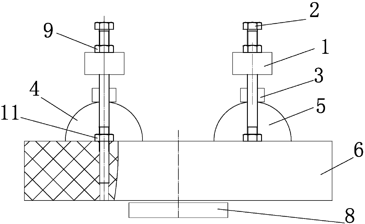
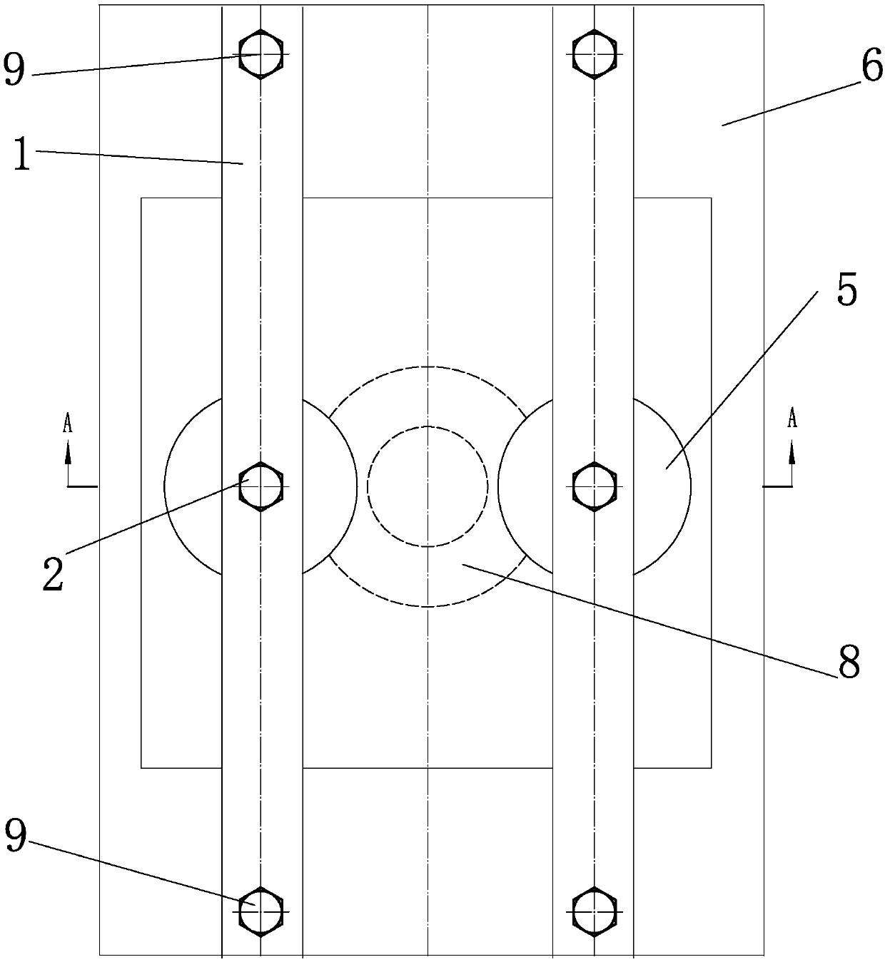
[0032] like figure 1 , image 3 , Figure 4 As shown, a planar electrode structure suitable for vacuum surface flashover includes insulating fasteners 1, high-voltage electrodes 4, ground electrodes 5, insulating supports 6, insulators 7 under test, electrode fixing bolts 2, and fixing nuts 3 , Sample fixing bolt 8, bolt two 9, groove 10, lock nut 11.

[0033] A groove 10 is provided in the middle of the upper part of the insulating support 6, and the tested insulator 7 cooperates with the groove 10. The high-voltage electrode 4 and the ground electrode 5 are in surface contact with the tested insulator 7. The high-voltage electrode 4 and the ground electrode 5 are in surface contact. The upper part is connected with the electrode pressing mechanism, and is kept in close contact with the tested insulator 7 through the pressing mechanism, and the insulating fastener is connected with the lower insulating support through the support.

[0034] The electrode...

Example Embodiment

[0043] Example 2

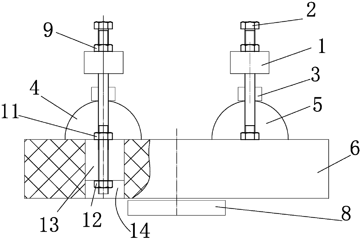
[0044] like figure 2 , Figure 5 As shown, the bottom of the insulating support 6 is provided with an opening 14, and the top of the bottom opening 14 is provided with a slotted hole 13, and a nut 2 12 is arranged in the slotted hole 13, and the nut 2 12 is threadedly matched with the lower end of the bolt 2 9. Since the slotted hole 13 is provided on the upper part of the bottom opening, the second nut 12 and the second bolt 9 can move left and right in the slotted hole 13, and the distance between the high voltage electrode 4 and the ground electrode 5 can be adjusted at will, and the adjustment range of the discharge gap is wide. It is conducive to scientific research and engineering simulation, has a wider range of use, and has better practical application value and promotion value.


PUM


Abstract

The invention discloses a planar electrode structure suitable for vacuum surface flashover, including an insulating fastener, a high voltage electrode, a ground electrode, an insulating bracket and aninsulator to be measured. A groove is arranged in the middle of the upper part of the insulating bracket, and the insulator to be measured and the groove are matched. The high voltage electrode and the ground electrode are in surface contact with the insulator to be measured. The high voltage electrode and the upper part of the ground electrode are connected with a pressing mechanism, and the clamping mechanism keeps the close contact with the insulator to be measured. The pressing mechanism includes the insulating fastener, an electrode fixing bolt I and a fixing bolt I. The electrode fixingbolt I is connected with the insulating fastener. The fixing bolt I is matched with the electrode fixing bolt I. The insulating fastener is connected with the insulating bracket at the lower part through a support piece. The planar electrode structure has the advantages of simple structure, good discharge stability, small influence of the gap electric field of the vacuum surface flashover, reduction in the discharge dispersion of the vacuum surface flashover, high reliability, strong operability, long service life, and small influence of the electrode fixing and the insulating support structure on the gap electric field.

Description

technical field [0001] The invention relates to the technical field of high-voltage vacuum discharge, in particular to a planar electrode structure suitable for surface flashover in vacuum. Background technique [0002] In the prior art, engineering research on vacuum surface flashover is usually based on an abstract model obtained from engineering practice. In this process, the arrangement of electrodes has a very significant impact on the test results. According to the difference between the electrode structure and the contact mode of the insulating medium, the typical electrode system experimental models can be divided into three categories, namely the parallel plate electrode system, the needle-plate electrode system and the planar electrode structure. [0003] The parallel plate electrode system is a commonly used structural model in the early study of vacuum surface flashover. This model is suitable for cylindrical and conical samples with axisymmetric structural geome...

Claims


Application Information

Patent Timeline
IPC IPC(8): G01R31/16
CPCG01R31/16
Inventor 张振军辜超姚金霞李杰任敬国师伟孙景文郑建孙艳迪孙承海王辉李秀卫袁海燕王斌张丕沛朱庆东王建
Owner ELECTRIC POWER RESEARCH INSTITUTE OF STATE GRID SHANDONG ELECTRIC POWER COMPANY
Why Eureka
Try Eureka