Trapped wave controllable ultra-wide-band antenna

An ultra-wideband antenna and notch technology, applied in the field of notch controllable ultra-wideband antennas, to achieve the effects of improving impedance matching, increasing impedance bandwidth, and high practical value

Pending Publication Date: 2018-02-16
SHANXI UNIV
View PDF0 Cites 15 Cited by
  • Summary
  • Abstract
  • Description
  • Claims
  • Application Information

AI Technical Summary

Problems solved by technology

[0003] In recent years, scholars at home and abroad have proposed a variety of notch controllable UWB antennas, but their common feature is that the antenna can only achieve single-band notch or dual-band notch. How to design a UWB antenna with multi-band notch controllability Antennas are a technical problem that still needs to be solved

Method used


Image

  • Trapped wave controllable ultra-wide-band antenna
  • Trapped wave controllable ultra-wide-band antenna
  • Trapped wave controllable ultra-wide-band antenna

Examples


Embodiment Construction

[0024] Below in conjunction with accompanying drawing, the embodiment of the present invention is described in detail:

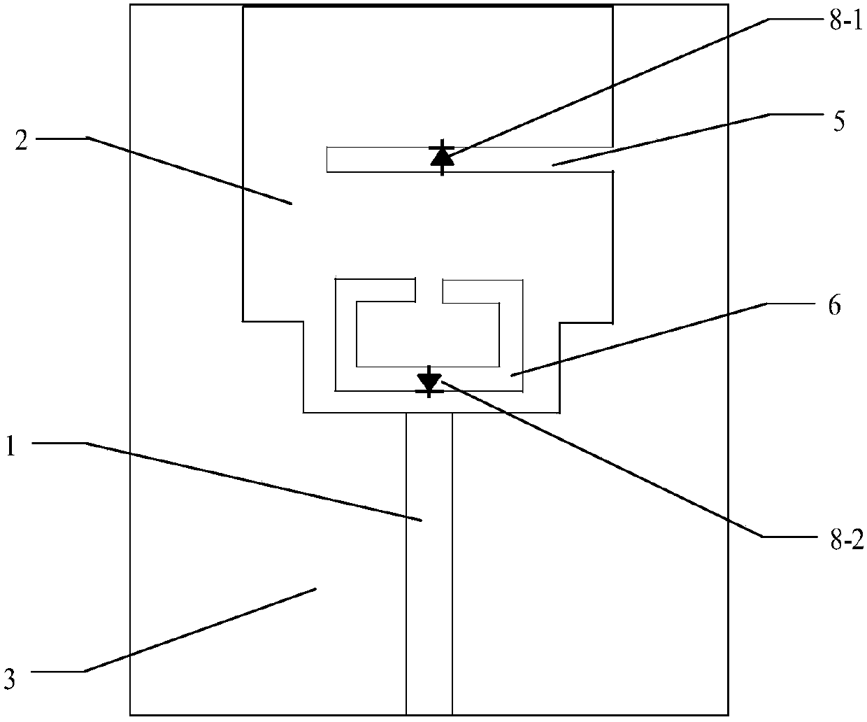
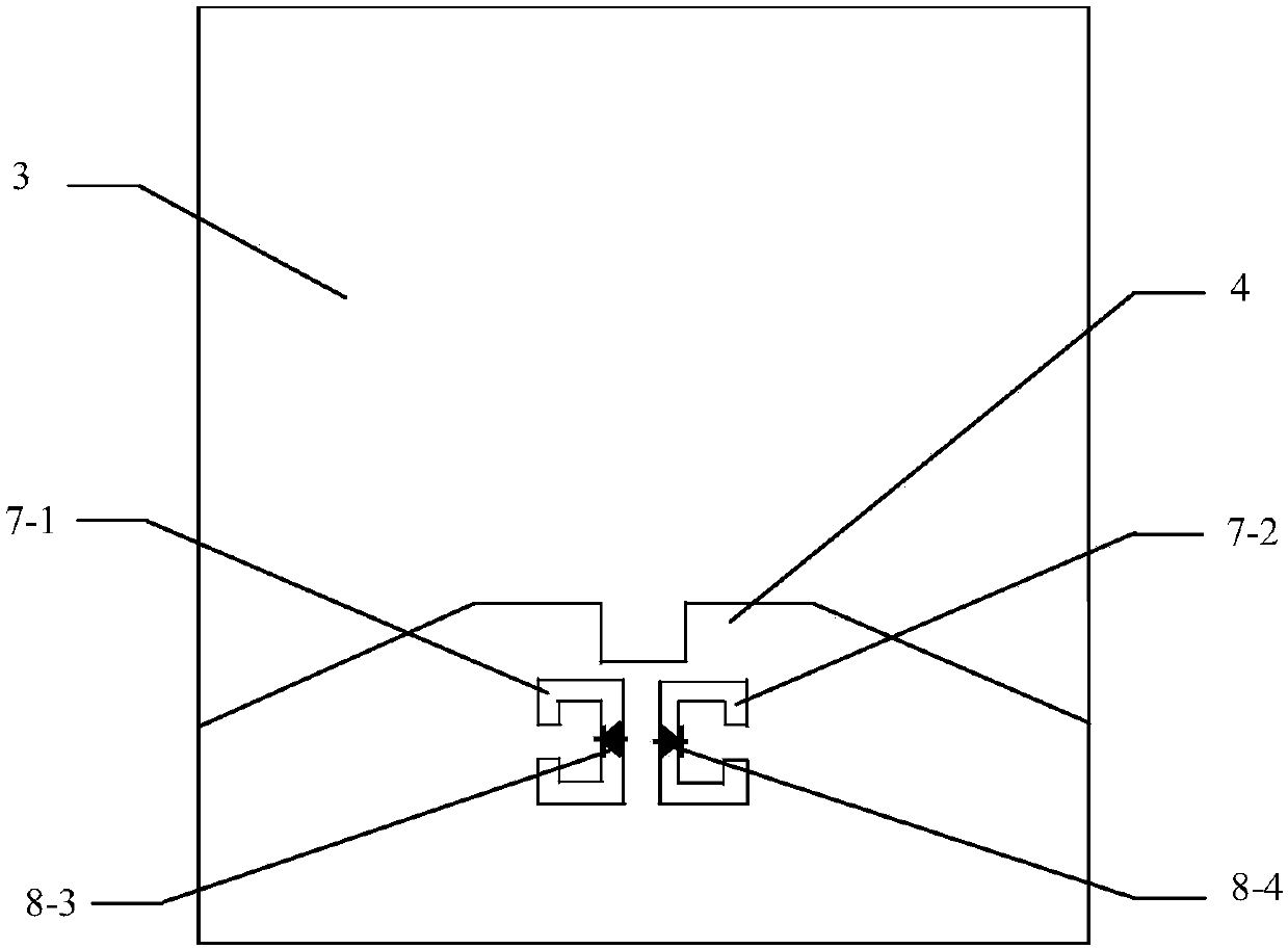
[0025] as attached figure 1 , figure 2 As shown, a notch controllable ultra-wideband antenna includes a microstrip feeder 1, a radiation unit 2, a dielectric substrate 3, and a ground plate 4; the microstrip feeder 1 and the radiation unit 2 are upper layers, and the dielectric substrate 3 is The middle layer is located below the microstrip feeder 1 and the radiating unit 2, the radiating unit 2 is located above the microstrip feeder 1, and the ground plate 4 is the lower layer located below the dielectric substrate 3; the radiating unit 2 is a chamfered A rectangular patch, an open circuit slot 5 and a split resonant ring 6 are opened on the radiation unit 2, and the open circuit slot 5 extends from the right edge of the radiation unit 2 into the radiation unit 2; the split resonator ring 6 is located Below the open gap 5, it is symmetrical to a centerli...


PUM

PropertyMeasurementUnit
Thicknessaaaaaaaaaa
Lengthaaaaaaaaaa
Widthaaaaaaaaaa

Abstract

The invention belongs to the technical field of an antenna in a communication system, and specifically relates to a trapped wave controllable ultra-wide-band antenna. The trapped wave controllable ultra-wide-band antenna comprises a microstrip feeder line, a radiation unit, a dielectric substrate and a grounding plate; the microstrip feeder line and the radiation unit are arranged on the upper layer, the dielectric substrate is arranged in the middle layer and positioned below the microstrip feeder line and the radiation unit, and the grounding plate is arranged on the lower layer and positioned below the dielectric substrate; an open circuit gap and an opening resonance ring are arranged on the radiation unit, and the open circuit gap extends from the right side edge of the radiation unitto the interior of the radiation unit; a first opening resonance ring and a second opening resonance ring are arranged on the grounding plate; the open circuit gap and the opening resonance ring areloaded with a first PIN diode and a second PIN diode respectively; and the first opening resonance ring and the second opening resonance ring are loaded with a third PIN diode and a fourth PIN diode respectively. The trapped wave controllable ultra-wide-band antenna can realize ultra wide band, single band wave trapping, dual band wave trapping and triple band wave trapping, and is simple in structure and suitable for the ultra-wide-band wireless communication system.

Description

technical field [0001] The invention belongs to the technical field of antennas in communication systems, and in particular relates to a notch controllable ultra-wideband antenna. Background technique [0002] Ultra-wideband technology has the advantages of low cost, high data transmission rate, and strong anti-interference ability. Since the US Federal Communications Commission applied the 3.1-10.6GHz frequency band to the commercial field in 2002, ultra-wideband technology has become a research hotspot in the field of short-distance wireless communication. . In the ultra-broadband communication system frequency band, there are some narrowband wireless communication systems, such as WiMAX frequency band (3.3-3.6GHz), C-band (3.7-4.2GHz), WLAN frequency band (5.15-5.35GHz, 5.725-5.825GHz) and ITU frequency band (8.025-8.4GHz), these narrowband systems interfere with each other with ultra-wideband communication systems. In order to reduce the interference between ultra-wide...

Claims


Application Information

Patent Timeline
IPC IPC(8): H01Q1/38H01Q1/50H01Q1/42H01Q5/20
CPCH01Q1/38H01Q1/42H01Q1/50H01Q5/20
Inventor 韩丽萍韩国瑞成根张文梅
Owner SHANXI UNIV
Why Eureka
Try Eureka