Cold-heat composite manufacturing method for machining of hollow turbine blade inner cavity precision casting appearance

A technology of turbine blade and precision casting, which is applied in the field of cold and heat composite manufacturing of precision casting shape machining of hollow turbine blade inner cavity, can solve the problems of air film hole deflection, difficult fixing of ceramic core, eccentric core, etc. The effect of manufacturing yield, improving manufacturing accuracy, and reducing manufacturing costs

Active Publication Date: 2018-02-23
枣庄北航机床创新研究院有限公司 +1
View PDF9 Cites 15 Cited by
  • Summary
  • Abstract
  • Description
  • Claims
  • Application Information

AI Technical Summary

Problems solved by technology

[0005] (1) It is difficult to fix the position of the ceramic core in the mold shell and it is difficult to ensure a stable and correct geometric position between it and the mold shell; The design size of the core wall thickness is very different
During the investment casting process, due to the core floating and moving under the action of molten metal, the position of the core is deviated, so that the shape and size of the airfoil inner cavity and the wall thickness between the airfoil and the outer shape of the airfoil do not meet the requirements. The eccentric and exposed cores are serious;
[0006] (2) The position of the ceramic core will change and deform during the molding process and casting process, and its position will deviate from the set original positioning reference, which will cause problems such as deflection of the air film hole when the blade is processed according to the external reference, which is serious Affect the cooling effect;
[0007] (3) The thickness of many tiny structures on the blade is very small, and it is difficult to fill the molten metal, which may easily lead to casting defects of the blade;
[0008] (4) Defects such as casting trachoma are prone to appear on the surface layer of the blade, making the blade a waste product

Method used


Image

  • Cold-heat composite manufacturing method for machining of hollow turbine blade inner cavity precision casting appearance
  • Cold-heat composite manufacturing method for machining of hollow turbine blade inner cavity precision casting appearance
  • Cold-heat composite manufacturing method for machining of hollow turbine blade inner cavity precision casting appearance

Examples


specific Embodiment

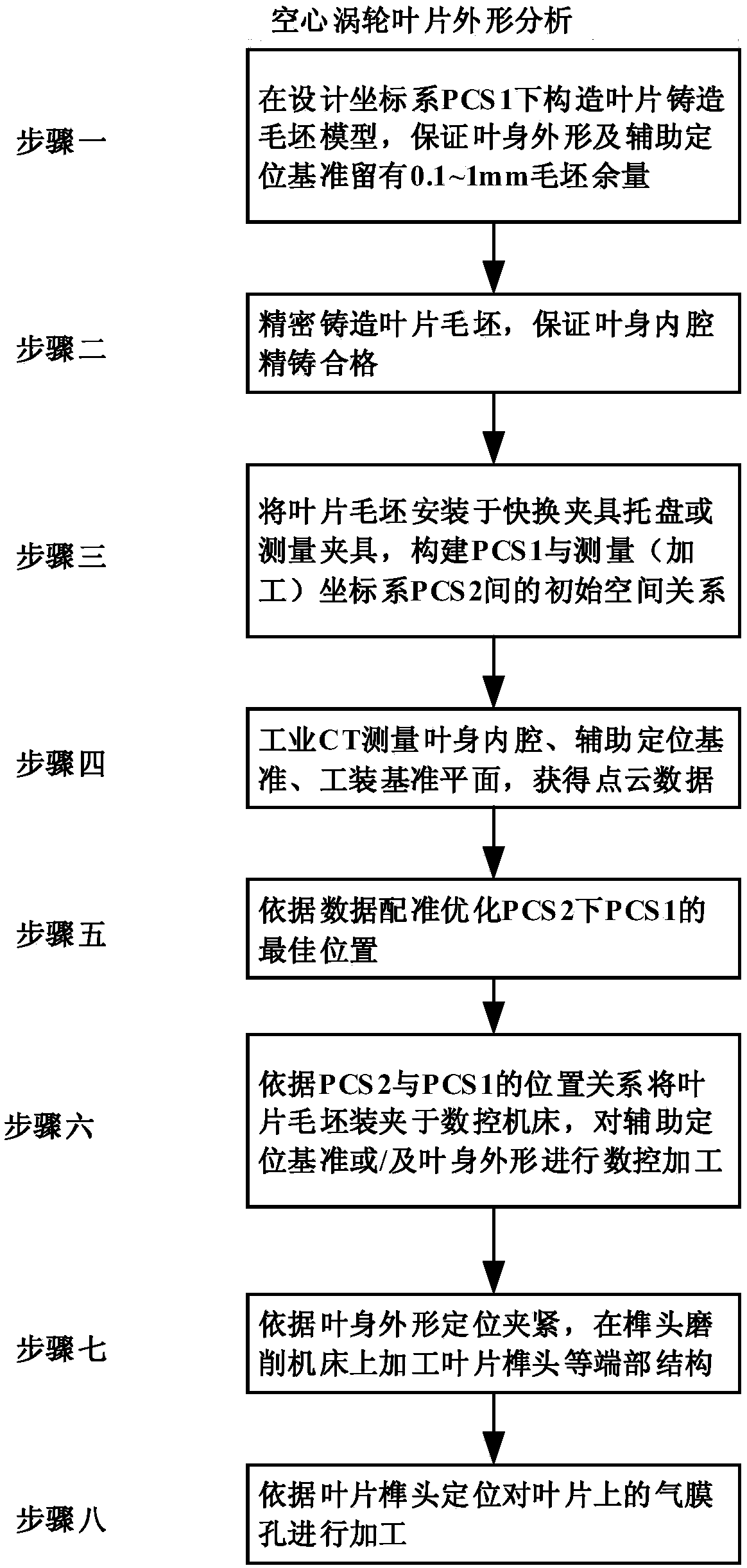
[0051] The technical process of the present invention is as figure 1 As shown, the specific implementation includes the following steps:

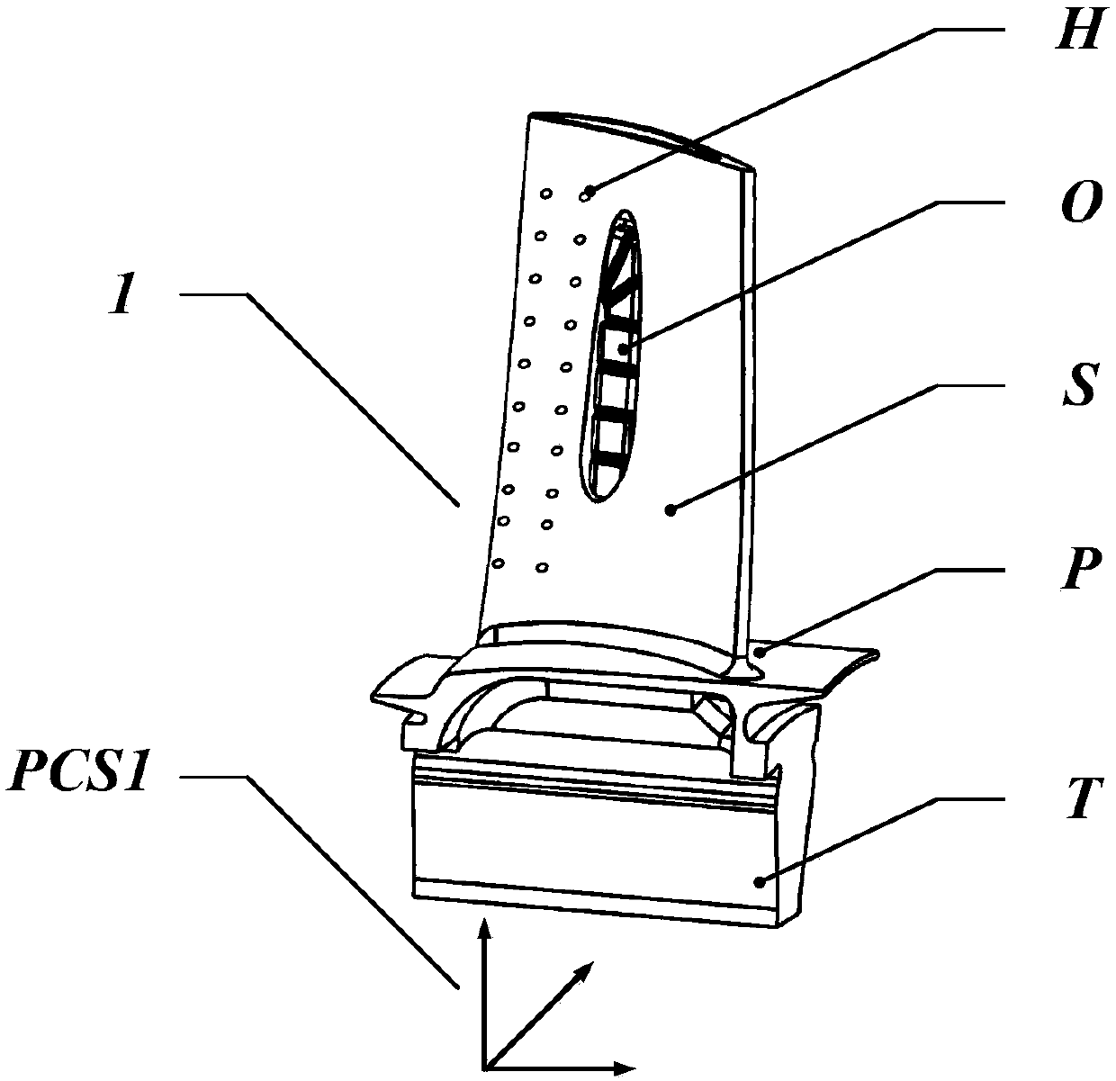
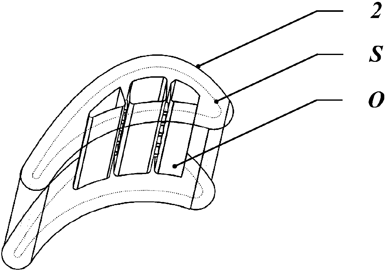
[0052] step one figure 2 It shows the front view of the hollow turbine blade design model 1 that needs to be manufactured by investment casting technology. The blade design model 1 includes tenon T, edge plate P, airfoil shape S, airfoil inner cavity O, air film hole H, blade Design model benchmark PCS1. image 3 It is the basic idea proposed by the present invention to solve the problem that the wall thickness does not meet the design requirements and the position deviation between the airfoil shape S and the airfoil inner cavity O due to the core shift caused by the investment casting process, the airfoil shape After the machining allowance d is left in S, the thickened casting blank 2 of the blade is obtained, so as to machine the shape S of the airfoil. At the same time, based on the requirements of the subsequent processing technol...


PUM


Abstract

The invention discloses a cold-heat composite manufacturing method for machining of the hollow turbine blade inner cavity precision casting appearance. The method comprises the steps that a turbine blade casting blank model is designed, a blade blank is cast, and the blade six-freedom-degree positioning datum point or the blade equivalent structure of the six-freedom-degree positioning datum pointis reserved; a rapid replacement clamp tray or a measuring clamp is arranged on a blade rabbet part, and accurate positioning of the blade is conducted; an industrial CT measuring device is used forobtaining point cloud data of a blade inner cavity, the blade inner shape and appearance, other related surfaces, auxiliary positioning datum and the like, a coordinate system is designed after fitting, and grinding machining or milling machining is conducted on the auxiliary positioning datum on the blade and the blade body appearance; the blade is positioned and clamped according to the machinedblade body appearance, and a tenon grinding machine tool is utilized for machining a blade tenon and other end portion structures; and air film holes in the blade are machined through tenon positioning. The casting process is simplified, meanwhile, the blade inner cavity and appearance manufacturing precision is guaranteed, the strict requirement for precision of the relative position of the blade inner cavity and the blade appearance is guaranteed, and the hollow turbine blade manufacturing qualification rate can be obviously increased.

Description

technical field [0001] The present invention relates to a manufacturing technology of a hollow turbine blade of an aero-engine, in particular to a cold-heat composite manufacturing method of precision casting and mechanical processing of the inner cavity of a hollow turbine blade, and is especially suitable for manufacturing by combining a precision casting method and a mechanical processing method Hollow turbine blades. Background technique [0002] The hollow turbine blades can be cooled by the low-temperature gas ejected from the air film hole, which can significantly reduce the high-temperature gas after the engine burns and melt the turbine blades. Usually, the method of increasing the temperature in front of the turbine is an effective way to improve the efficiency of the engine, but this This method can make the temperature of the high-temperature gas exceed the melting point of the turbine blade, so how to manufacture a high-quality turbine blade with a large number ...

Claims


Application Information

Patent Timeline
Patent Type & Authority Applications(China)
IPC IPC(8): B23P15/02
CPCB23P15/02
Inventor 张云陈志同夏峥嵘全芳朱正清
Owner 枣庄北航机床创新研究院有限公司
Why Eureka
Try Eureka