Xenon lamp and manufacturing technology thereof

A technology for xenon lamps and lamp holders, which is applied in the field of xenon lamps, can solve the problems of complex processing technology, shortened service life, and low manufacturing pass rate, and achieve the effects of good light transmission, high pressure leakage prevention, and high manufacturing pass rate

CN106373859AActive Publication Date: 2017-02-01四川梦天节能科技有限公司
8 Cites 2 Cited by

Patent Information

Authority / Receiving Office
CN · China
Patent Type
Applications(China)
Current Assignee / Owner
Publication Date
2017-02-01

Smart Images

  • Figure 1
    Figure 1
  • Figure 2
    Figure 2
  • Figure 3
    Figure 3
Patent Text Reader

Abstract

The invention relates to a xenon lamp and a manufacturing technology thereof. The xenon lamp comprises a lamp holder, a lamp tube and a luminescent tube arranged in the lamp tube, wherein the lamp holder comprises a fixed seat and a connector arranged at one end of the fixed seat; the connector is internally provided with a cavity for installing the lamp tube; the fixed seat is internally provided with two connecting passages; one end of each of the two connecting passages is communicated with the cavity respectively, and one of the other ends of the two connecting passages is communicated to the outside of the side wall of the fixed seat, and the other of the other ends of the two connecting passages is communicated to the lower end face of the fixed seat; two electrode leads of the luminescent tube are arranged in the two connecting passages respectively; one end of each of the two electrode leads is connected with a molybdenum sheet respectively, the molybdenum sheets of the two electrode leads are arranged in a staggered manner and are arranged in a clamping and sealing port and the lamp tube respectively, an insulating sleeve is arranged on the molybdenum sheet positioned in the lamp tube in a sleeving manner, and one end of the insulating sleeve stretches out of the clamping and sealing port along the corresponding electrode lead. By using a clamping and sealing technology, the required time of the manufacturing process is short, and the manufacturing qualified rate is high; the connecting process between the lamp tube and the lamp holder is simple, and the reliability of connection between the lamp tube and the lamp holder is improved.
Need to check novelty before this filing date? Find Prior Art

Description

technical field

[0001] The invention relates to the technical field of xenon lamps, in particular to a xenon lamp and a manufacturing process thereof. Background technique

[0002] HID (High Intensity Discharge) high-pressure gas discharge lamp, also known as xenon lamp, its working principle is in (UV-CUT) anti-ultraviolet crystal quartz glass tube, filled with inert gases such as xenon (XENON) and iodide, and then stabilized Supercharger (also known as supercharger), which instantly supercharges ordinary civilian commercial electricity to pulse oscillation electric energy of about 23000V through frequency conversion, and stimulates the xenon electrons in the quartz tube to dissociate through high-voltage oscillation to generate a jump arc between the two electrodes to complete the lighting. process, and then provide a square wave voltage with a pulse width period of 2.38 milliseconds that can adapt to the tube pressure of the lamp tube to maintain the normal light emission...

Examples

Embodiment Construction

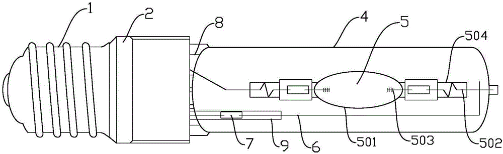
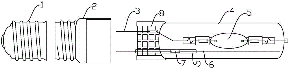
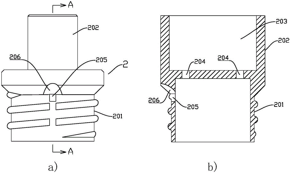
[0028] The present invention will be further described below in conjunction with the accompanying drawings and specific embodiments.

[0029] like figure 1 and 2 , the xenon lamp in this embodiment includes a lamp cap 2, a lamp tube 4 and a luminous tube 5 arranged in the lamp tube 4, a clip seal 8 is provided at the end of the lamp tube 4, and two electrode leads 3 of the luminous tube 5 pass through the clip Sealing 8, the lamp cap 2 includes a fixing seat 201 and a connecting head 202 arranged at one end of the fixing seat 201, a cavity 203 for installing a lamp tube is arranged in the connecting head 202, two connecting channels are arranged in the fixing seat 201, and the two connecting channels One end is respectively connected to the cavity 203 , and the other ends of the two connecting passages are connected to the outside of the side wall of the fixing seat 201 , and the other is connected to the lower end surface of the fixing seat 201 . like image 3 As shown, on...