
Integral annular conveying belt

An endless conveyor belt and conveyor belt technology, applied in the field of conveyor belts, can solve the problems of increased space occupation of the drive motor, asynchronous operation of the conveyor belt, and affecting the transfer effect of workpieces, etc., to save space, prevent asynchronous operation, and excellent Effects of insulation and aging resistance

Pending Publication Date: 2018-02-23
ZHANGJIAGANG HUASHEN INDAL RUBBER PRODS
View PDF0 Cites 4 Cited by
  • Summary
  • Abstract
  • Description
  • Claims
  • Application Information

AI Technical Summary

Problems solved by technology

Traditionally, in order to make the assembly line achieve circular circulation, an endless conveyor belt is usually used. The existing endless conveyor belt is composed of two sets of parallel conveyor belts used in conjunction with a drive motor and a turntable mechanism with joints at both ends. The conveyor belt often runs Asynchronous, different operating speed phenomenon, which affects the transfer effect of the workpiece
Since two drive motors are used to drive the conveyor belt to run, the drive motors will increase the space occupied and the problem of increased energy consumption will also arise

Method used


Image

  • Integral annular conveying belt
  • Integral annular conveying belt
  • Integral annular conveying belt

Examples


Embodiment 1

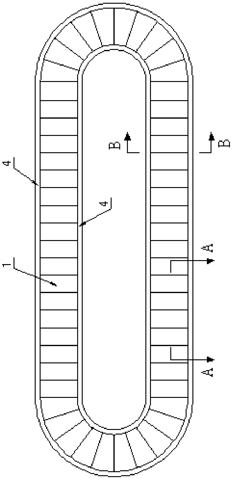
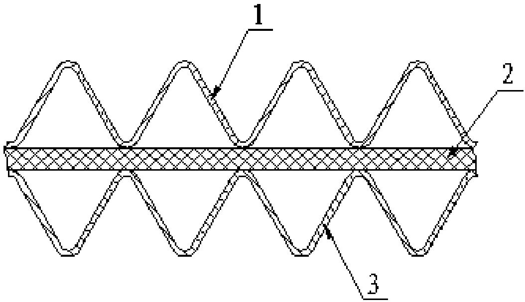
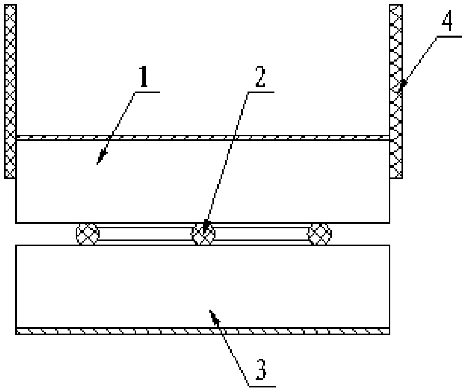
[0020] Embodiment 1: a kind of integral endless conveyer belt, as Figure 1 ~ Figure 3 As shown, including the upper base layer 1 of the conveyor belt, the skeleton of the conveyor belt 2, the lower base layer 3 of the conveyor belt and the soft baffle 4, the upper base layer 1 of the conveyor belt and the lower base layer 3 of the conveyor belt are folded organ-shaped bodies to form a ring-shaped overall conveyor belt The upper base layer 1 of the conveyor belt and the lower base layer 3 of the conveyor belt are formed by needle punching of an aramid fiber layer and an industrial filament cloth layer, the industrial filament cloth layer is a nylon filament cloth layer, and the aramid fiber layer is wool Mesh short fiber layer, three conveyor belt skeletons 2 are equidistantly arranged between the conveyor belt upper base 1 and the conveyor belt lower base 3, and the conveyor belt skeleton 2 is along the direction of enclosing the conveyor belt upper base 1 and the conveyor low...

Embodiment 2

[0021] Embodiment 2: The difference from Embodiment 1 is that the upper base layer 1 of the conveyor belt and the lower base layer 3 of the conveyor belt are formed by needle punching of aramid fibers and non-alkali glass fiber cloth layers.

Embodiment 3

[0022] Embodiment 3: The difference from Embodiment 1 or 2 is that the outer covering layer is a rubber covering layer.


PUM


Abstract

The invention relates to an integral annular conveying belt which comprises a conveying belt upper basic layer, conveying belt frameworks and a conveying belt lower basic layer. The conveying belt upper basic layer and the conveying belt lower basic layer are folding organ-shaped bodies and form the integral annular conveying belt in a defining manner. The at least two conveying belt frameworks are arranged between the conveying belt upper basic layer and the conveying belt lower basic layer. The conveying belt frameworks are fixedly connected with the conveying belt upper basic layer and theconveying belt lower basic layer in the defining direction of the conveying belt upper basic layer and the conveying belt lower basic layer. The conveying belt frameworks are steel wire ropes. An outer covering layer is arranged above the conveying belt upper basic layer. The integral conveying belt can directly revolve to form an annular shape in a defining manner; the phenomena that due to use of two sets of parallel conveying belts used in cooperation, operation is not synchronous, and the operation speeds have differences are avoided; the workpiece transfer effect is guaranteed; space andenergy are saved; the service life is long; and products are light, and transporting and mounting are convenient.

Description

Technical field: [0001] The invention relates to a conveyor belt, in particular to an integral endless conveyor belt. Background technique: [0002] With the continuous development of industrial automation technology, the production workshops of most enterprises use assembly lines to transfer workpieces in order to improve production and transportation efficiency. The conveyor belt, as the key equipment of the assembly line, plays the role of supporting and transferring workpieces. Traditionally, in order to make the assembly line achieve circular circulation, an endless conveyor belt is usually used. The existing endless conveyor belt is composed of two sets of parallel conveyor belts used in conjunction with a drive motor and a turntable mechanism with joints at both ends. The conveyor belt often runs The phenomenon of out of synchronization and difference in operating speed will affect the transfer effect of the workpiece. Since two driving motors are used to drive the c...

Claims


Application Information

Patent Timeline
Patent Type & Authority Applications(China)
IPC IPC(8): B65G15/30B65G15/36B65G15/56
CPCB65G15/30B65G15/36B65G15/56
Inventor 周国荣赵恺
Owner ZHANGJIAGANG HUASHEN INDAL RUBBER PRODS
Learn More