High-efficiency and energy-saving device of fuel engine

A fuel-fired engine, high-efficiency and energy-saving technology, applied in engine components, machines/engines, fuel heat treatment devices, etc., can solve the problems of large oil smell, black smoke, high temperature, etc., and achieve strong explosion power and less oil consumption. , the effect of high ignition point

Inactive Publication Date: 2018-02-23
蒙山县生产力促进中心
View PDF2 Cites 0 Cited by
  • Summary
  • Abstract
  • Description
  • Claims
  • Application Information

AI Technical Summary

Problems solved by technology

[0002] At present, direct fuel injection, spark plugs, electric injection, etc. are commonly used in the field of fuel engines. These engines have the following disadvantages: first, the compression ratio of the piston in the cylinder produces high temperature and high heat is not enough; second, the engine consumes too much fuel, and the exhaust gas smells The third is that there is a lot of black smoke when accelerating during the working process, and black smoke is emitted by sparks; the fourth is that the engine is under load and the horsepower is insufficient, and the endurance is insufficient; fifth is that the exhaust pipe of the engine is working at night. When starting, it causes white smoke and blue smoke from the exhaust pipe of the engine, and the smell of stinky oil is very strong; Seventh, there may even be water droplets from the exhaust pipe; Eighth, the piston ring groove of the engine and the valve seat of each cylinder breathe too much carbon Ninth, the noise reduction of the engine is too large; Tenth, the intake air is not enough when the engine is under load and running at high speed
The main reason for the above shortcomings is that the engine air intake to each cylinder piston is mixed with cold air and fuel, resulting in insufficient high temperature and high heat generated by the explosion of the compression ratio, and about 10-15% of the mixed gas in the piston cylinder is discharged from the piston without sufficient combustion. Out of cylinder

Method used


Image

  • High-efficiency and energy-saving device of fuel engine
  • High-efficiency and energy-saving device of fuel engine
  • High-efficiency and energy-saving device of fuel engine

Examples


Embodiment Construction

[0014] The following will clearly and completely describe the technical solutions in the embodiments of the present invention with reference to the accompanying drawings in the embodiments of the present invention. Obviously, the described embodiments are only some, not all, embodiments of the present invention. Based on the embodiments of the present invention, all other embodiments obtained by persons of ordinary skill in the art without making creative efforts belong to the protection scope of the present invention.

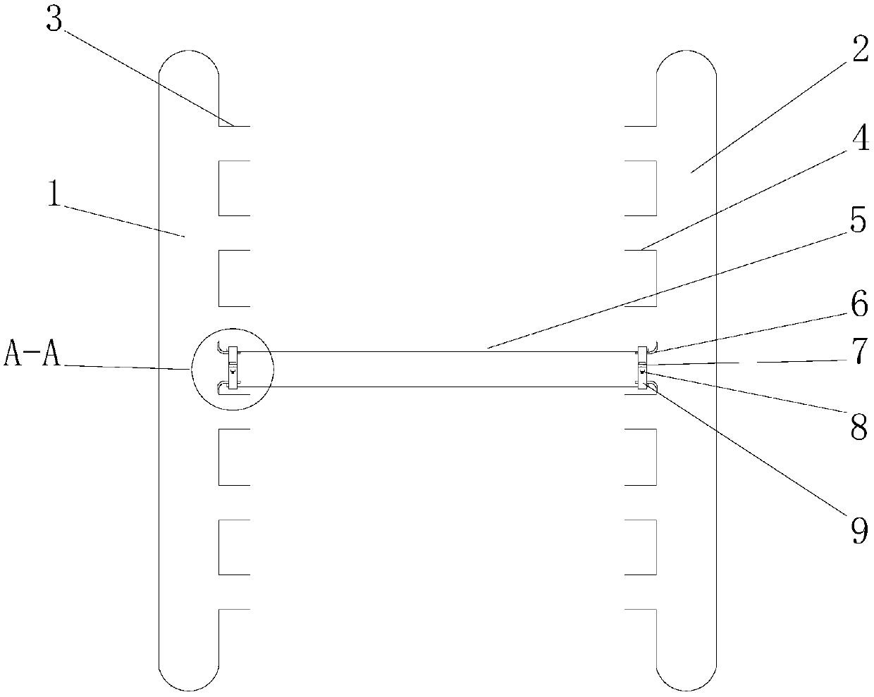
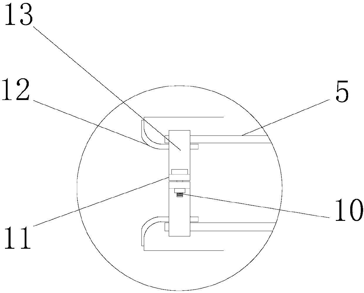
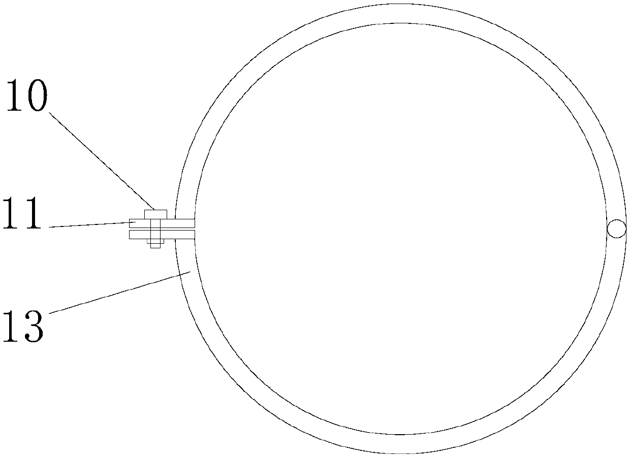
[0015] see Figure 1-3 , a high-efficiency energy-saving device for a fuel engine, comprising a total intake pipe 1 and a total exhaust pipe 2, the total intake pipe 1 and the total exhaust pipe 2 are connected through a connecting pipe 5, and one side of the total intake pipe 1 is provided with an air inlet 3. One side of the air inlet 3 is provided with an air inlet connecting pipe 12, the outside of the air inlet connecting pipe 12 is sleeved with a connect...


PUM


Abstract

The invention discloses a high-efficiency and energy-saving device of a fuel engine. The high-efficiency and energy-saving device comprises a main gas inlet pipe and a main exhaust pipe. Intake gas inlets are formed in one side of the main gas inlet pipe. The outer portion of a gas inlet connecting pipe is connected with a connecting pipe in a sleeved manner. A first fixed ring is mounted on the outer portion of the joint of the gas inlet connecting pipe and the connecting pipe. A gas outlet connecting pipe is connected in the other end of the connecting pipe in a sleeved manner. The gas outlet connecting pipe is arranged on one side of the main exhaust pipe. Exhausted gas outlets are formed in one side of the main exhaust pipe. According to the high-efficiency and energy-saving device ofthe fuel engine, an exhausted gas high-temperature and high-heat pipeline of the engine is connected with and communicates with a gas inlet pipeline, and after the engine is started, a large amount ofhigh-temperature and high-heat good air of exhausted gas is absorbed by intake gas into various piston air cylinders to become excellent fuel mixed gas; the ignition point is high; little oil is utilized; brisance is strong; sufficient combustion can be achieved; and therefore the above defects of the fuel engine are overcome, fuel oil which is not sufficiently combusted originally is sufficiently combusted, and the aims of high efficiency and energy saving are achieved.

Description

technical field [0001] The invention relates to the technical field of energy-saving devices, in particular to a high-efficiency energy-saving device for a fuel engine. Background technique [0002] At present, direct fuel injection, spark plugs, electric injection, etc. are common in the field of fuel engines. These engines have the following disadvantages: first, the compression ratio of the piston in the cylinder produces high temperature and high heat is not enough; second, the engine consumes too much fuel, and the exhaust gas smells The third is that there is a lot of black smoke when accelerating during the working process, and black smoke is emitted by sparks; the fourth is that the engine is under load and the horsepower is insufficient, and the endurance is insufficient; fifth is that the exhaust pipe of the engine is working at night. When starting, it causes white smoke and blue smoke from the exhaust pipe of the engine, and the stinky oil smell is very strong; S...

Claims


Application Information

Patent Timeline
Patent Type & Authority Applications(China)
IPC IPC(8): F02M31/08
CPCF02M31/08
Inventor 刘寿远
Owner 蒙山县生产力促进中心
Why Eureka
Try Eureka