Dielectric barrier discharge plasma flat-plate turbulence flow drag reduction device

A dielectric barrier discharge and plasma technology, applied in the direction of plasma, electrical components, etc., can solve the problems of reducing the performance of aircraft, not applicable to aircraft engineering applications, and difficult to realize wall cooling method, and achieves novel structure, low manufacturing cost, and easy The effect of mass production

Pending Publication Date: 2018-02-23
ZHEJIANG UNIV
View PDF11 Cites 9 Cited by
  • Summary
  • Abstract
  • Description
  • Claims
  • Application Information

AI Technical Summary

Problems solved by technology

Traditional boundary layer control techniques, such as the air-blowing method, require engine bleed air, which will reduce the performance of the aircraft. The wall cooling method is more difficult to achieve in flight and is not suitable for actual aircraft engineering applications

Method used


Image

  • Dielectric barrier discharge plasma flat-plate turbulence flow drag reduction device

Examples


Embodiment Construction

[0012] The present invention will be described in further detail below in conjunction with the examples, the following examples are explanations of the present invention and the present invention is not limited to the following examples.

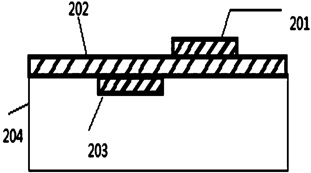
[0013] Such as figure 1 As shown, a dielectric barrier discharge plasma turbulent drag reduction device includes a bare electrode 201 , an insulating dielectric layer 202 , and a covering electrode 203 . In appearance, the exposed electrode 201 and the covered electrode 203 are rectangular in shape, and the insulating dielectric layer 202 is rectangular. The exposed electrode 201 and the covered electrode 203 are located on two surfaces of the insulating medium layer 202 respectively, and are staggered forward and backward.

[0014] In this example, the electrode flow lengths of the exposed electrode 201 and the covered electrode 203 are both 2.65 mm, and the size of the insulating medium layer is L×W×H=300×20×1.5 mm.

[0015] The device i...


PUM


Abstract

The invention discloses a dielectric barrier discharge plasma flat-plate turbulence flow drag reduction device, which comprises upper and lower layer electrodes and an insulating dielectric layer arranged between the upper and lower layer electrodes. The upper and lower layer electrodes are connected with a high-voltage high-frequency power supply separately. The upper and lower layer electrodes are arranged in an asymmetrical manner relative to the insulating dielectric layer, and are staggered back and forth. When in use, the upper and lower layer electrodes are electrified with the high-voltage high-frequency power supply, so that air of surfaces of the drag reduction device is ionized, and charged particles move in a directed manner along an electric field under the action of an electric field force and collide with neutral air gas molecules, thereby inducing an air flow in the area to do directional movement to form a continuous jet flow. The dielectric barrier discharge plasma flat-plate turbulence flow drag reduction device has the advantages of simple working conditions, low cost, simple structure and easy mass production.

Description

technical field [0001] The invention relates to a dielectric barrier discharge plasma turbulent drag reducing device. Background technique [0002] Boundary layer control is an important research field in fluid mechanics. In turbulent boundary layers, quasi-swirl vortices are closely related to large wall frictional drag. The generation of Reynolds stress is closely related to the dynamic development of the vortex structure near the wall. The resistance change is the result of the combination of vortex structure and mass transport caused by the penetrating force acting on the fluid. Traditional boundary layer control techniques, such as the air-breathing method, require engine bleed air, which will reduce the performance of the aircraft. The wall cooling method is more difficult to achieve in flight and is not suitable for actual aircraft engineering applications. Therefore, novel plasma active flow control techniques applied to the boundary layer have been developed. ...

Claims


Application Information

Patent Timeline
Patent Type & Authority Applications(China)
IPC IPC(8): H05H1/24
CPCH05H1/2406H05H1/2443
Inventor 郑耀邹建锋叶志贤楼韫闻童小康闾曾怡俞天纬陈烨斯张永兴
Owner ZHEJIANG UNIV
Why Eureka
Try Eureka