PCB rapid in heat dissipation

A fast, heat sink technology, applied in the direction of circuit heating devices, printed circuit components, electrical components, etc., can solve the problem of low heat dissipation performance of PCB, achieve the effect of improving heat dissipation performance, saving external space, and reducing overall size

Active Publication Date: 2018-02-23
DONGGUAN SHENGYI ELECTRONICS
View PDF4 Cites 7 Cited by
  • Summary
  • Abstract
  • Description
  • Claims
  • Application Information

AI Technical Summary

Problems solved by technology

[0008] The purpose of the present invention is to provide a PCB with rapid heat dissipation, which can solve the problem of low heat dissipation performance of existing PCBs

Method used


Image

  • PCB rapid in heat dissipation
  • PCB rapid in heat dissipation
  • PCB rapid in heat dissipation

Examples


Embodiment 1

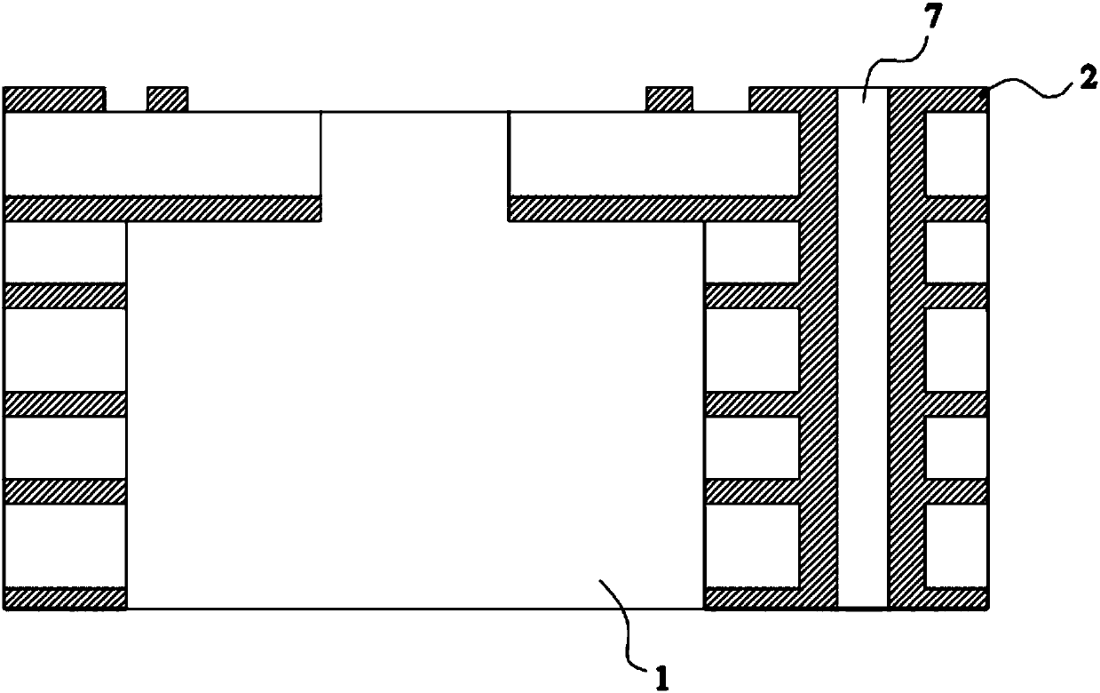
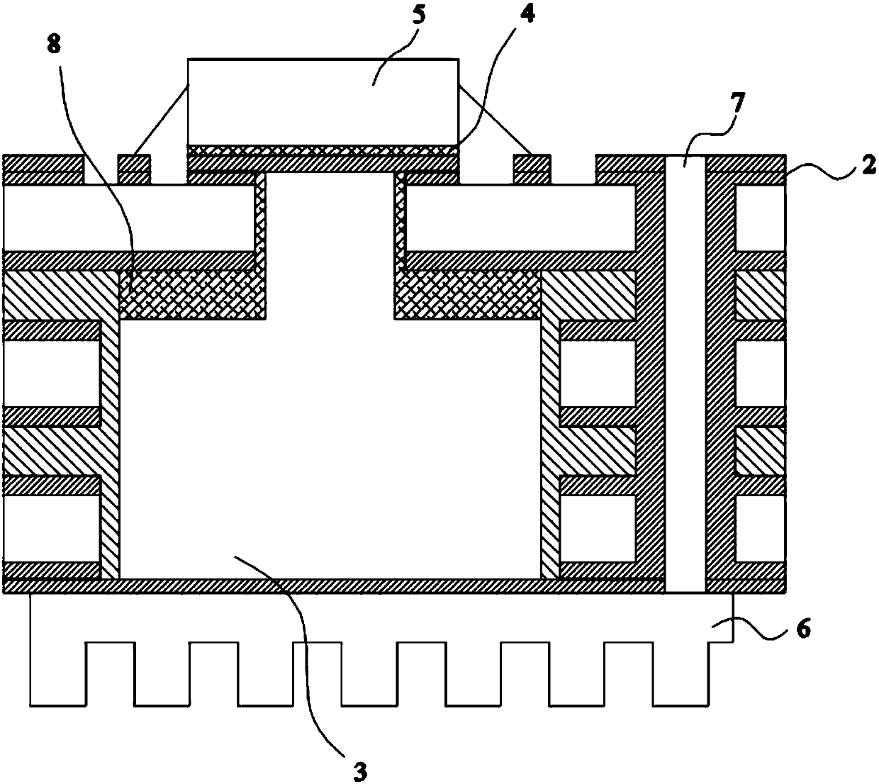
[0034] This embodiment provides a PCB with rapid heat dissipation, wherein the PCB is formed by pressing three core boards (but the number is not limited to this), and the schematic diagram of slotting on the PCB is as follows figure 1 shown. On the PCB, a stepped groove 1 is milled by a milling machine, and a via hole 7 is drilled by a drilling machine, wherein both are arranged along the thickness direction of the PCB, and the shoulder of the stepped groove 1 is connected to one of the metal layers 2 inside the PCB. Contour. The via hole 7 is electrically connected to the metal layer 2 of the PCB, and is a metallized hole. In addition, the top surface of the PCB is pre-installed with high-power components 5 , and the opening position of the stepped groove 1 corresponds to the bottom position of the pre-installed high-power components 5 .

[0035] The via hole 7 is provided to transfer the heat in the metal layer 2 inside the PCB to the via hole 7 to play the role of auxili...

Embodiment 2

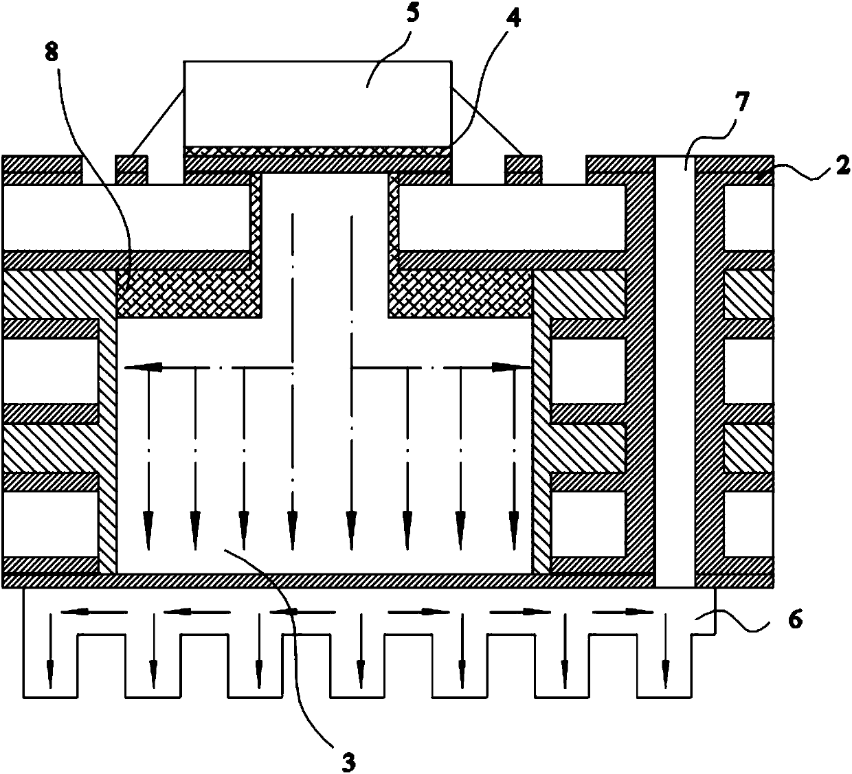
[0050] This embodiment provides another PCB with rapid heat dissipation. Its cross section is Figure 5 As shown, for the sake of simplicity, only the differences between Embodiment 2 and Embodiment 1 are described. The difference is:

[0051] In this embodiment, the structure of the stepped high thermal conductivity metal block 3 and the heat sink 6 is combined, that is, the sheet structure on the heat sink 6 is arranged on the stepped high thermal conductivity metal block 3, so that the stepped high thermal conductivity metal block 3 is Evenly distributed flake structure. Other structures are the same as those in Embodiment 1, and will not be repeated here.

Embodiment 3

[0053] This embodiment provides a PCB with rapid heat dissipation, its cross-sectional view is as follows Figure 6 As shown, for the sake of simplicity, only the differences between Embodiment 3 and Embodiment 1 are described. The difference is:

[0054] The bottom surface of the stepped metal block 3 with high thermal conductivity protrudes from the bottom surface of the PCB, and the heat sink 6 is arranged close to the stepped metal block 3 with high thermal conductivity. Other structures are the same as those in Embodiment 1, and will not be repeated here.

[0055] In the known structure, after adopting the heat conduction metal layer 2, the heat is conducted to the air by the heat sink 6, however, the more media the generated heat passes through, the less heat the heat sink 6 dissipates. The medium of spreading scriptures will absorb most of the heat, but cannot dissipate it. Therefore, the structure in this embodiment can dissipate heat more quickly and directly.

[...


PUM


Abstract

The invention relates to the field of circuit boards, and discloses a PCB rapid in heat dissipation. The PCB comprises a stepped groove and a stepped high-thermal-conductivity metal block which is arranged in the stepped groove, and solder paste is arranged between the top surface of the stepped high-thermal-conductivity metal block and a high-power component on the surface of the PCB; a conductive heat-conducting adhesive sheet is arranged between the shoulder of the stepped high-thermal-conductivity metal block and a metal layer adjacent to the stepped high-thermal-conductivity metal block.The stepped groove is formed in the PCB and the stepped high-thermal-conductivity metal block is embedded in the stepped groove so that heat generated by the high-power component and the metal layer in the PCB can be transmitted into air through the stepped high-thermal-conductivity metal block in time, the heat dissipation performance of the PCB is improved, the structure is simple, and the PCB is more convenient to process and install.

Description

technical field [0001] The invention relates to the field of circuit boards, in particular to a PCB with rapid heat dissipation. Background technique [0002] PCB (Printed Circuit Board), that is, printed circuit board, is the provider of electrical connections for electronic components. The multi-layer PCB is made by pressing the core board and the prepreg. With the development of electronic product technology, the trend of surface mount and miniaturization of components is becoming more and more obvious, the density of products is increasing, the main frequency of components is increasing, and the power consumption of individual components is gradually increasing, resulting in the increase of heat flux density. sharply increased. Therefore, in order to ensure the service life of electronic equipment, it is necessary to solve the problem of heat dissipation of high-power components. [0003] The heat dissipation problem at the mounting position of high-power components c...

Claims


Application Information

Patent Timeline
Patent Type & Authority Applications(China)
IPC IPC(8): H05K1/02
CPCH05K1/0204H05K2201/10416
Inventor 肖璐纪成光王洪府李民善
Owner DONGGUAN SHENGYI ELECTRONICS
Why Eureka
Try Eureka