Novel safety and emergency hydraulic brake

A hydraulic brake and safety technology, applied in the direction of fluid pressure actuating device, fluid pressure actuating system components, servo motors, etc., can solve the problems of unable to be shipped, not guaranteed safety, too fast brake opening, etc. The effect of safe, fast and controllable release of heavy objects, reducing the probability of accidents and smooth work flow

Pending Publication Date: 2018-02-27
JIANGXI GONGBU MACHINERY
View PDF0 Cites 9 Cited by
  • Summary
  • Abstract
  • Description
  • Claims
  • Application Information

AI Technical Summary

Problems solved by technology

[0006] 1. When the motor suddenly loses power due to the failure of the power supply, the electric pump stops running, and the oil pressure in the rod chamber of the single-acting cylinder cannot rise steadily, so that the brake's opening action stops, and the items on the hook cannot be shipped. Delayed works
[0007] 2. Although the manual pump can manually supply oil to the single-acting cylinder to maintain pressure, its oil supply pressure cannot be accurately and effectively controlled. If the pressure is too small, the brake will open slowly and reduce efficiency; if the pressure is too high, the brake will open too quickly. , when the transfer hook has not been in place, the item is hung on the hook that has been opened, and there is a risk of falling at any time, and the safety cannot be guaranteed

Method used


Image

  • Novel safety and emergency hydraulic brake
  • Novel safety and emergency hydraulic brake
  • Novel safety and emergency hydraulic brake

Examples


Embodiment Construction

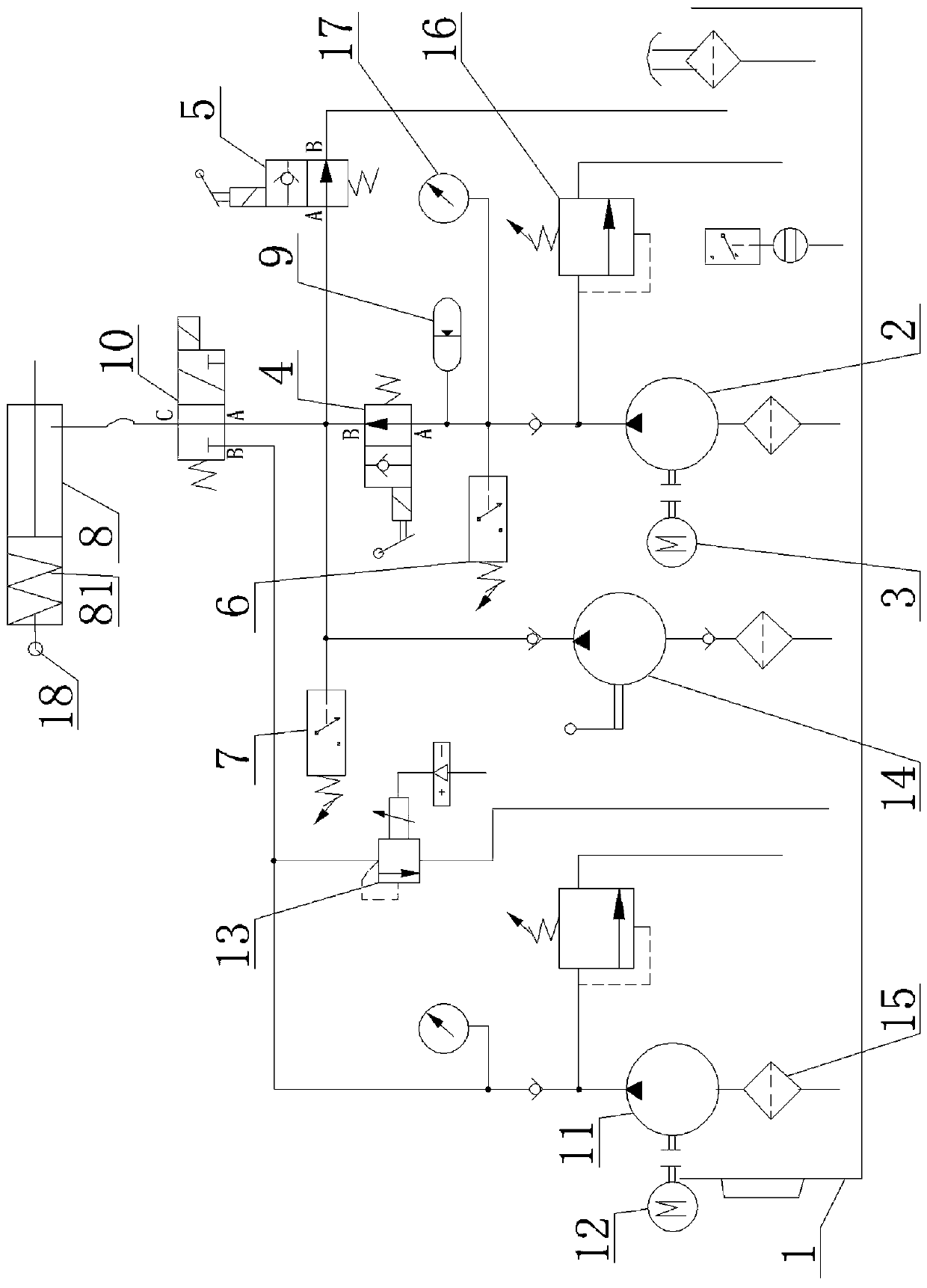
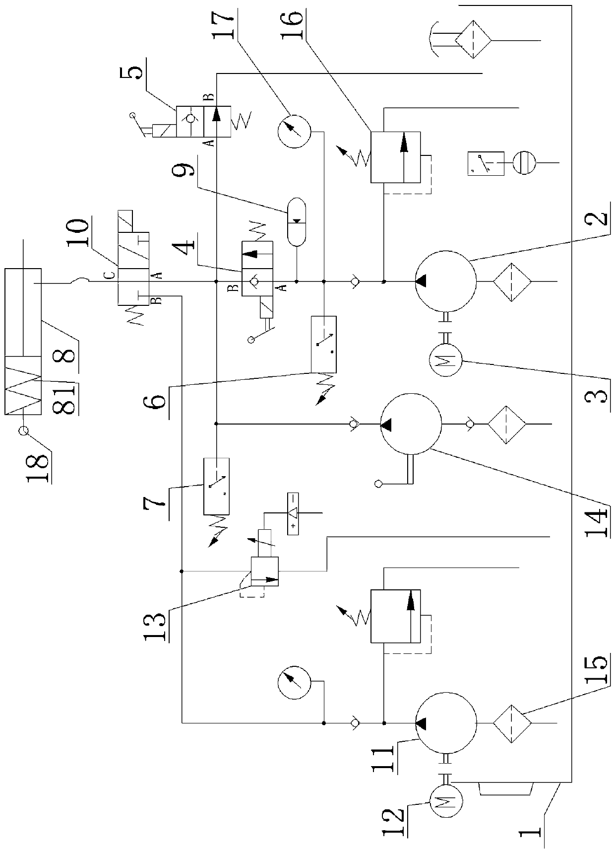
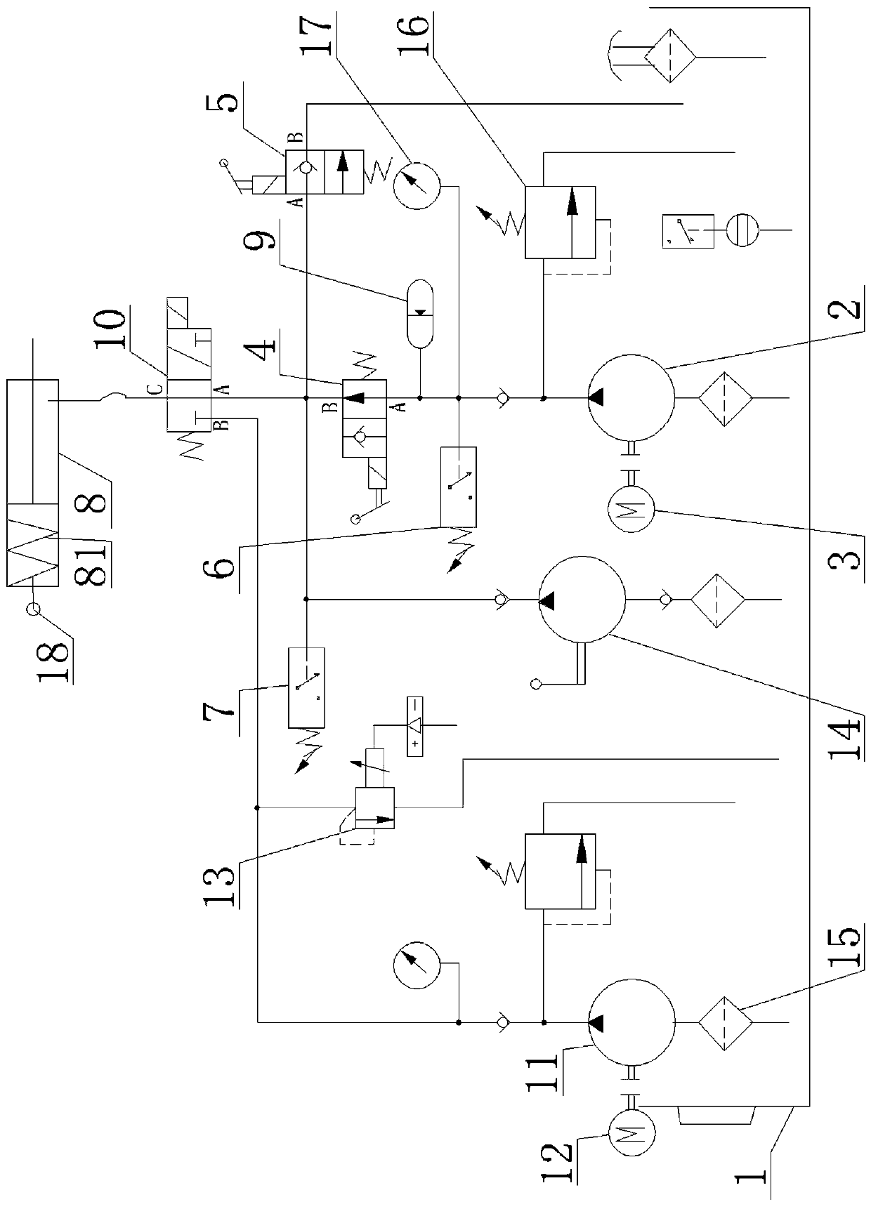
[0027] From Figure 1 to Figure 4 It can be seen that the novel safety emergency hydraulic brake of the present invention includes a fuel tank 1, a main oil supply system, a single-acting oil cylinder 8, a two-position three-way solenoid valve 10, an emergency oil supply system, a proportional overflow valve 13, and a spring compression amount Detector 18 and controller, wherein the main oil supply system includes main oil pump 2, main motor 3, normally open first electromagnetic reversing valve 4, normally open second electromagnetic reversing valve 5, first pressure relay 6, The second pressure relay 7 and the accumulator 9, the emergency oil supply system includes an emergency oil pump 11 and an emergency motor 12, and a closing spring 81 for closing and clamping is installed in the rodless cavity of the single-acting oil cylinder 8;

[0028] The oil suction ports of the main oil pump 2 and the emergency oil pump 11 are connected to the oil tank 1; the main motor 3 and the ...


PUM


Abstract

The invention discloses a novel safety and emergency hydraulic brake. The novel safety and emergency hydraulic brake comprises an oil tank, a main oil supplying system, a single-acting oil cylinder and a controller and also comprises a proportional overflowing valve and an emergency oil supplying system, wherein the emergency oil supplying system and the main oil supplying system are powered by different power supplies; one end of the emergency oil supplying system is connected with the oil tank and the other end of the emergency oil supplying system is connected onto an oil path between the main oil supplying system and the single-acting oil cylinder in series by a two-position three-way electromagnetic valve; the proportional overflowing valve is connected onto an oil path between the emergency oil supplying system and the two-position three-way electromagnetic valve in parallel; the emergency oil supplying system is driven by the controller and supplies oil to the single-acting oilcylinder to carry out gate-opening release action when the main oil supplying system is powered-off; the proportional overflowing valve is adjusted by the controller to control the emergency oil supplying system to supply oil to the single-acting oil cylinder stably. The novel safety and emergency hydraulic brake disclosed by the invention has the advantages that continuous and stable gate openingcan be ensured when a main motor of a normally-closed type brake is powered-off, and a hoisting mechanism can be guaranteed to release heavy objects in a safe-fast-controllable manner when the systemis powered-off, so that the probability of accidents is reduced.

Description

technical field [0001] The invention relates to the field of brakes, in particular to a novel safety emergency hydraulic brake. Background technique [0002] A brake is a device that has the functions of decelerating, stopping or keeping a moving part (or a moving machine) in a stopped state. It is a mechanical part that stops or slows down a moving part in a machine, commonly known as a brake or a brake. [0003] Brakes can be divided into two categories: industrial brakes and automobile brakes. Among industrial brakes, crane brakes are both working devices and safety devices for cranes. Stop at the required height, or control the speed of lifting or lowering. In mechanisms such as running or luffing, the brake can make the mechanism stop smoothly at the required position. [0004] In order to ensure the safety during the hoisting process of the crane hook, the normally closed hydraulic brake is basically used for locking and hoisting on the hook. Such as Figure 5 As sho...

Claims


Application Information

Patent Timeline
IPC IPC(8): B66D5/26F15B11/08F15B21/04
CPCF15B11/08F15B21/041B66D5/26
Inventor 陈程郑庆华喻连生向斌
Owner JIANGXI GONGBU MACHINERY
Why Eureka
Try Eureka