
Mask and filming method and filming device thereof

A reticle and directional technology, applied in coating, vacuum evaporation plating, electric solid device and other directions, can solve the problem of large gap between the substrate to be formed and the inner convex pattern.

Active Publication Date: 2018-02-27
BOE TECH GRP CO LTD +1
View PDF2 Cites 13 Cited by
  • Summary
  • Abstract
  • Description
  • Claims
  • Application Information

AI Technical Summary

Problems solved by technology

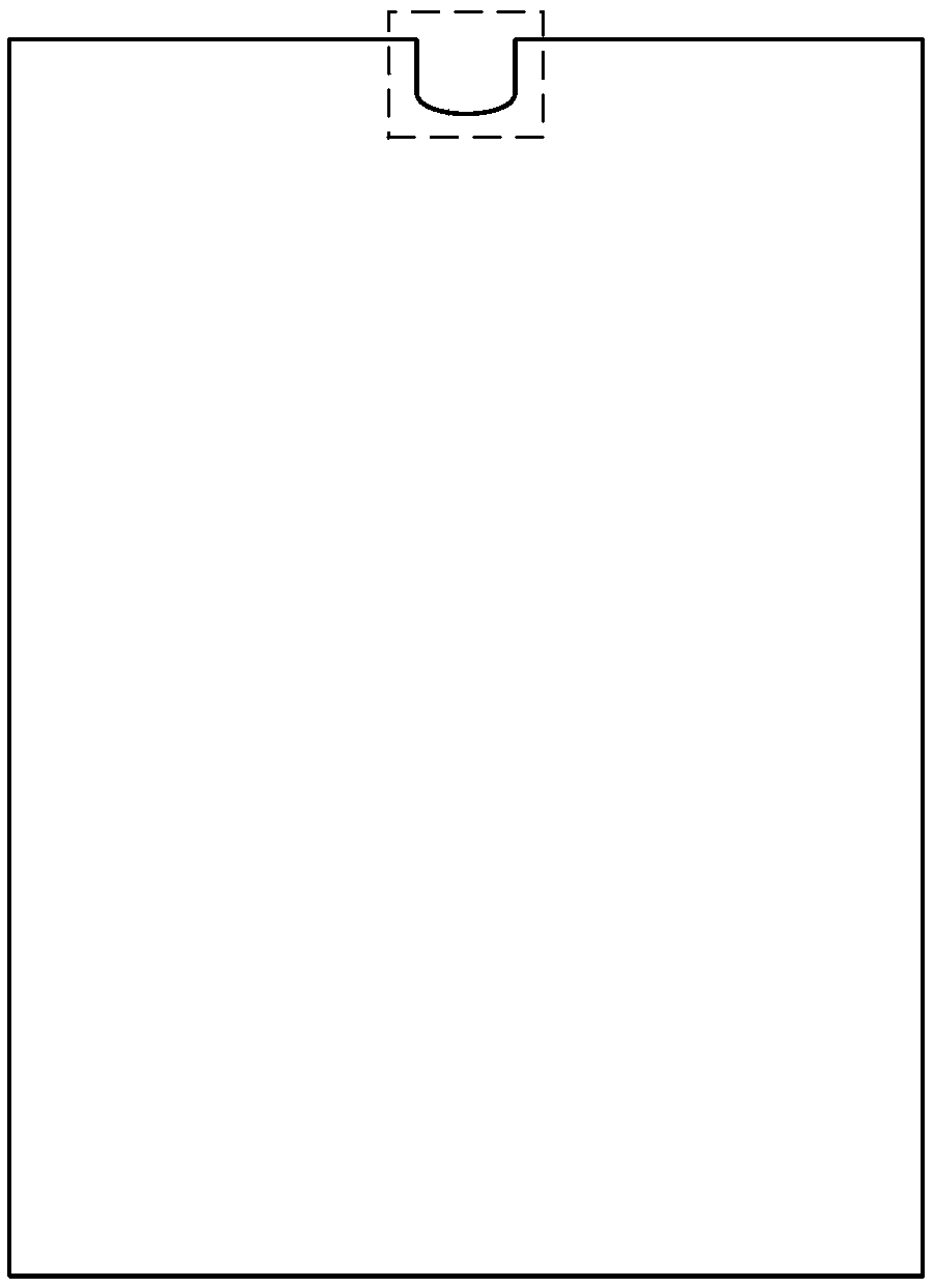
[0005] Embodiments of the present invention provide a reticle, its film forming method, and film forming equipment, which can solve the problem of the tension caused by the inner convex pattern when the mask pattern is stretched and fixed when the mask pattern on the reticle includes an inner convex pattern. Unevenness will cause upturning, resulting in a large gap distance between the substrate to be filmed and the convex pattern

Method used


Image

  • Mask and filming method and filming device thereof
  • Mask and filming method and filming device thereof
  • Mask and filming method and filming device thereof

Examples


Embodiment Construction

[0033] The following will clearly and completely describe the technical solutions in the embodiments of the present invention with reference to the accompanying drawings in the embodiments of the present invention. Obviously, the described embodiments are only some, not all, embodiments of the present invention. Based on the embodiments of the present invention, all other embodiments obtained by persons of ordinary skill in the art without making creative efforts belong to the protection scope of the present invention.

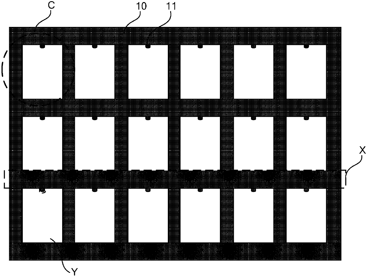
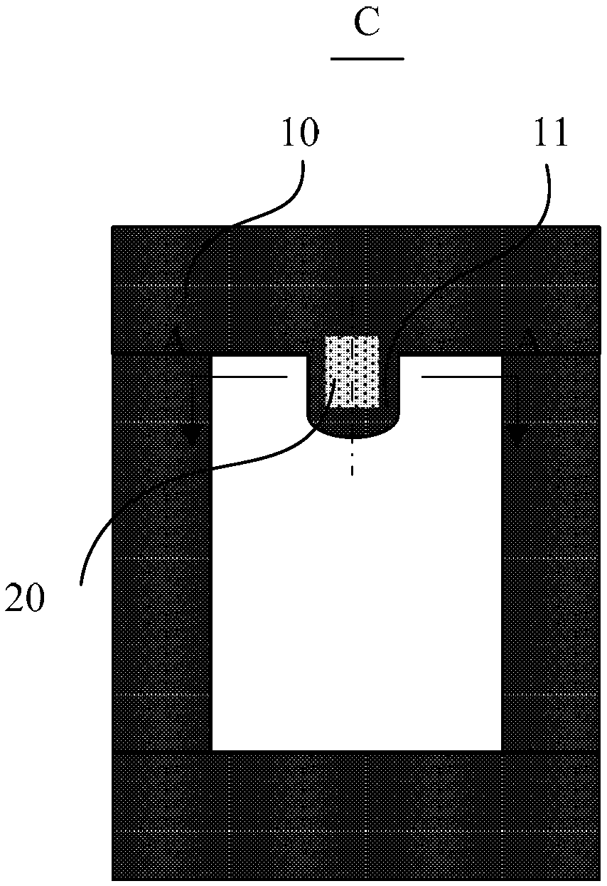
[0034] An embodiment of the present invention provides a mask, such as figure 2 As shown, the reticle includes a shielding portion X and a hollowed-out area Y, and the shielding portion X includes a shielding strip 10 and a convex portion 11 extending into the hollowed-out area Y along the width direction of the shielding strip 10 . A recessed area 20 is disposed on the upper surface or the lower surface of the reticle, wherein the recessed area 20 is located...


PUM


Abstract

The invention provides a mask and a filming method and a filming device thereof, and relates to the technical field of display and can solve the problem that if a mask pattern in the mask includes aninner convex pattern, when the mask is spread and fixed, the inner convex pattern can be cocking-up due to the uneven tensile force, so that the gap distance between the to-be-filmed base plate and the inner convex pattern is large. The mask includes a shielding part and a hollow area. The shielding part includes a shielding strip and a convex part stretching into the hollow area along the width direction of the shielding strip. The upper surface or the lower surface of the mask pattern is provided with a concave area, wherein the concave area is located or partly located in the convex part.

Description

technical field [0001] The invention relates to the field of display technology, in particular to a mask plate, a film forming method, and film forming equipment. Background technique [0002] Organic Light Emitting Diode (OLED) display devices have been widely used in computers, mobile phones, etc. In various electronic devices including electronic products. [0003] In the prior art, fabricating a film structure on a base substrate can usually be accomplished by vacuum evaporation coating, physical vapor deposition film formation or chemical vapor deposition film formation. Among them, for the film structure that needs to be deposited and formed after forming a new substance through a chemical reaction during the gas phase doping process, it is necessary to use the method of chemical vapor deposition to form a film. Chemical vapor deposition is due to its equipment structure Simple, mature process and strong adhesion of the film deposited after the reaction, so it is wid...

Claims


Application Information

Patent Timeline
Patent Type & Authority Applications(China)
IPC IPC(8): C23C16/04H01L51/56H10K99/00
CPCC23C16/042H10K71/164H10K71/166C23C14/042H10K71/00
Inventor 周桢力乔梓蒋志亮
Owner BOE TECH GRP CO LTD
Learn More